volvo s90 headlights,toyota alphard headlights,volvo xc90 led headlights,mclaren headlights PNP Car Light & SHARLOMAY LTD Company , https://www.pnpcarlight.com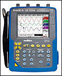 An oscilloscope is a widely used electronic measuring instrument. It can convert electric signals that are invisible to the naked eye into visible images, making it easier for people to study the changing process of various electrical phenomena. The oscilloscope uses a narrow electron beam consisting of high-speed electrons to create a tiny spot on a screen coated with a fluorescent material. Under the action of the signal under test, the electron beam is like a pen tip, which can depict the curve of the instantaneous value of the measured signal on the screen. Using an oscilloscope, you can observe the waveform curves of various signal amplitudes over time, and you can also use it to test various power levels, such as voltage, current, frequency, phase difference, amplitude, and so on.
Oscilloscope composition
Display circuit
The display circuit includes two parts of the oscilloscope tube and its control circuit. The oscilloscope is a special kind of electronic tube and is an important part of the oscilloscope. The oscilloscope consists of three parts: an electron gun, a deflection yoke, and a fluorescent screen.
(1) electron gun
Electron guns are used to generate and form high-speed, bunched electrons to bombard fluorescent screens. It is mainly composed of filament F, cathode K, control electrode G, first anode A1, and second anode A2. In addition to the filaments, the rest of the electrode structures are metal cylinders, and their axes are kept on the same axis. When the cathode is heated, electrons can be emitted in the axial direction; the control electrode is a negative potential with respect to the cathode, and changing the potential can change the number of electrons passing through the control hole, that is, controlling the brightness of the spot on the phosphor screen. In order to increase the brightness of the light spot on the screen without degrading the sensitivity to deflection of the electron beam, a post-acceleration electrode A3 is also added between the deflection yoke and the fluorescent screen in modern oscilloscopes.
The first anode adds a positive voltage of about several hundred volts to the cathode. A higher positive voltage is applied to the second anode than to the first anode. The electron beam passing through the control hole is accelerated under the action of the high potential of the first anode and the second anode, and moves toward the screen at a high speed. Due to the repulsion of the same charge, the electron beam will gradually spread out. Through the focusing action of the electric field between the first anode and the second anode, electrons are re-aggregated and converge at one point. By properly controlling the magnitude of the potential difference between the first anode and the second anode, the focus can be placed on the screen just to show a bright and fine dot. Changing the potential difference between the first anode and the second anode can act to adjust the focus of the spot, which is the principle of the oscilloscope's "focus" and "auxiliary focus" adjustments. The third anode is formed by coating the inner surface of the cone of the oscilloscope tube with a layer of graphite, usually with a very high voltage. It has three functions: 1 to further accelerate the electrons passing through the deflection yoke so that the electrons have enough energy to The screen is bombarded to obtain sufficient brightness; 2 Graphite layer is coated on the entire cone, which can play a shielding role; 3 Electron beam bombardment of the fluorescent screen generates secondary electrons, and A3 at a high potential can absorb these electrons.
Crt digital readout oscilloscope (2) deflection system
The deflecting system of the oscilloscope is mostly electrostatic deflection. It is composed of two pairs of parallel metal plates that are perpendicular to each other and are called the horizontal deflection plate and the vertical deflection plate. Separately controls the movement of the electron beam in the horizontal and vertical directions. When the electrons move between the deflecting plates, if there is no voltage applied to the deflecting plate, there will be no electric field between the deflecting plates. After leaving the second anode, the electrons entering the deflection system will move in the axial direction to the center of the screen. If there is a voltage on the deflecting plate, there will be an electric field between the deflecting plates, and the electrons entering the deflection system will be directed to the specified position of the fluorescent screen under the action of the deflecting electric field.
If the two deflection plates are parallel to each other and their potential difference is equal to zero, then the beam with the velocity 通过 passing through the space of the deflection plate will move along the original direction (set as the axis direction) and hit the coordinate origin of the screen. . If there is a constant potential difference between the two deflecting plates, an electric field is formed between the deflecting plates. This electric field is perpendicular to the moving direction of the electrons, so that the electrons are deflected toward the deflecting plate with a relatively high potential. In this way, in the space between the two deflecting plates, electrons make tangential motion at this point along the parabola. Finally, the electron lands on point A on the screen. This point A is a certain distance from the origin (0) of the screen. This distance is called the amount of deflection and is denoted by y. The amount of deflection y is proportional to the voltage Vy applied to the deflection plate. Similarly, a similar situation occurs when a DC voltage is applied to the horizontal deflection plate, but the light spot is deflected in the horizontal direction.
(3) The fluorescent screen is located at the end of the oscilloscope. Its role is to display the deflected electron beam for observation. The oscilloscope's fluorescent screen is coated with a layer of luminescent material. As a result, fluorescent spots appear on the screen where high-speed electrons are impacted. The brightness of the spot at this time is determined by the number, density, and speed of the electron beams. When the voltage at the gate is changed, the number of electrons in the electron beam will change, and the brightness of the spot will change. When using an oscilloscope, it is not advisable to have a very bright spot fixed on a position of the oscilloscope's fluorescent screen. Otherwise, the fluorescent material at this point will be burned out due to long-term electronic shocks and lose its luminous ability.
Fluorescent screens coated with different phosphors will display different colors and different afterglow times when exposed to electrons. Normally used for observing general signal waveforms are green-emitting, genus after-wave oscilloscope tubes for observation of non-periodic Sex and low-frequency signals use orange-yellow light, long-lasting oscilloscopes, and oscilloscopes for photography use blue short-wave afterglow oscilloscopes.
Vertical (Y-axis) amplification circuit
Because the deflection sensitivity of the oscilloscope tube is very low, for example, the commonly used oscilloscope 13SJ38J type, its vertical deflection sensitivity is 0.86mm/V (about 12V voltage produces 1cm deflection), so the general signal voltage to be measured must pass through The amplification of the vertical amplifying circuit is added to the vertical deflection plate of the oscilloscope to obtain a properly sized pattern in the vertical direction.
Horizontal (X-axis) amplification circuit
Since the deflection sensitivity of the oscilloscope is also low in the horizontal direction, the voltage (sawtooth voltage or other voltage) connected to the horizontal deflection board of the oscilloscope must first be amplified by the horizontal amplification circuit and added to the oscilloscope. Deflection the board horizontally to get an appropriately sized figure in the horizontal direction.
Scanning and synchronizing circuits
The scanning circuit generates a sawtooth wave voltage. The frequency of the sawtooth voltage can be continuously adjusted within a certain range. The role of the sawtooth voltage is to make the electron beam emitted from the cathode of the oscilloscope tube form a periodic, time-proportional horizontal displacement on the screen, ie, to form a time base line. In this way, the time-varying waveform of the measured signal applied in the vertical direction can be displayed on the screen.
Power supply circuit
The power supply circuit supplies the negative and high voltages, the filament voltage, and the like required for the vertical and horizontal amplification circuits, the scanning and synchronization circuits, and the oscilloscope and control circuits.
From the schematic functional block diagram of the oscilloscope, the measured signal voltage is added to the oscilloscope's Y-axis input and applied to the vertical deflection board of the oscilloscope through the vertical amplification circuit. The horizontal deflection voltage of the oscilloscope, although most of the cases use the sawtooth voltage (used for observing the waveform), other applied voltages (for measuring the frequency, phase difference, etc.) are sometimes used, so the input of the horizontal amplifying circuit is There is a horizontal signal selection switch to select the internal sawtooth voltage of the oscilloscope as required or to use other voltages applied to the input of the X axis as the horizontal deflection voltage.
In addition, in order to keep the pattern displayed on the fluorescent screen stable, it is required that the frequency of the sawtooth wave voltage signal and the frequency of the measured signal keep synchronized. In this way, not only the frequency of the sawtooth wave voltage can be continuously adjusted, but also a synchronization signal is input on the circuit that generates the sawtooth wave. In this way, for a simple oscilloscope (such as the domestic SB10 type oscilloscope) that can only generate a continuous scan (that is, generating a continuous, continuous sawtooth wave), it is necessary to input a frequency to the observed signal on its scanning circuit. The synchronization signal to contain the sawtooth wave oscillation frequency. For oscilloscopes that have a wait-to-scan function (that is, do not generate sawtooth waves at ordinary times, generate a saw-tooth wave when the signal is detected, and perform one scan) (such as domestic ST-16 oscilloscope, SR-8 double trace oscilloscope, etc. In this case, it is necessary to input a trigger signal related to the measured signal on its scanning circuit so that the scanning process closely matches the measured signal, and in order to adapt to various needs, the synchronization (or trigger) signal may be selected by the synchronization or trigger signal selection switch. To select, there are usually three sources: 1 from the vertical amplification circuit to the measured signal as a synchronous (or trigger) signal, this signal is called "internal synchronization" (or "inside trigger") signal; 2 introduce some related The external signal is a sync (or trigger) signal. This signal is called an “external sync†(or “external triggerâ€) signal. This signal is applied to the external sync (or external trigger) input. 3 Some oscilloscope sync signal selection switches have a The “power synchronization†of the file is a 220V, 50Hz power supply voltage, which is used as a synchronization signal after stepping down through the transformer secondary.