Combined Flow Closed Cooling Tower
Closed Cooling Tower is operated by circulating water or fluid, which is divided into two closed loops.
1. Circulation in the tower: the circulating water or fluid passes through the hot zone environment. After the water temperature rises, it enters the surface cooler in the tower, and the heat is sent to the environment outside the tower through the surface cooler and ventilation fan. The cooled circulating water or fluid is sent to the heat source by the water pump.
2. Circulation outside the tower: the spray water is sent to the spray system by the water tank through the water pipe. After spraying, the spray water first exchanges heat with the filler, so that the spray water can be cooled rapidly. At this time, the water contacts the surface of the surface cooler for heat exchange. Part of the hot steam is discharged through the ventilation fan, and the cooled spray water drops to the water tank for secondary circulation to form an external circulation for cooling.
Combined Flow Closed Cooling Tower,Bac Cooling Tower,Cooling Tower Systems,Chiller Tower Wuxi Ark Fluid Science Technology Co., Ltd. , https://www.fangzhouarkfluid.com
0 Introduction The measurement of the Young's modulus of metal materials is one of the necessary experiments in physics experiments in universities and engineering colleges. The key to the measurement of the Young's modulus of elasticity of a wire lies in the accurate measurement of the tiny length of the wire. Some laboratories in the country still use the optical lever method to measure the tiny length of the wire, and this measurement method is The adjustment of the optical path has strict requirements, which are difficult to measure and difficult to grasp, the operation is relatively tedious, and the reading process is error-prone and takes a long time. In response to the development status and development requirements of domestic university physics experiments, the use of high technology to continuously improve physical experimental equipment and to achieve automatic detection and control of experimental equipment has become a major trend. Therefore, we need to open up new measurement methods to improve experimental instruments.
1 Systematic overall design We first use the device that measures the Young's modulus to produce the tiny displacement, then uses the even beam to shine on the silicon photoelectricity battery, uses the baffle connected to the metal wire to place the light between the light source and the silicon photoelectricity battery, like chart As shown in Fig. 1, when the baffle is moved, the output current changes, and because the baffle light changes much, the output current has a corresponding amount of change (linear change), and then the electric signal is amplified and converted into a single-chip microcomputer. Since the program written in advance has been input into the SCM, real-time automatic measurement, data processing and display can be realized by the SCM, thereby achieving automation and high precision of Young's modulus measurement. After the operator only needs to be familiar with the operating instructions, he or she can use the keys on the keyboard to achieve the experimental requirements. The final result can be displayed on the LED display connected to the microcontroller. 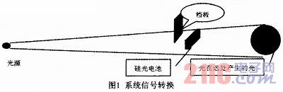
2 hardware part The hardware part mainly has the following modules: photoelectric conversion module composed of light source and silicon photocell; current-voltage conversion and amplification and filtering module composed of TL084 chip and its peripheral components; AD conversion module; The data processing and output module consisting of a microcontroller and an LCD are shown in Figure 2. The following two modules are briefly described below. 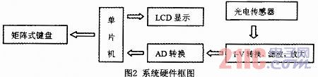
One-time fit: r=-0.04433x+86.4396
Quadratic fit: r=2.323e-005x^2-0.048232x+86.5482
Third-order fit: r=-3.2246e-007x^3+0.00010449x^2-0.053677x+86.6233
From the above equation, we can see that as the number of fittings increases, the order of the coefficients of the higher order terms becomes smaller and smaller, and the range of change is large. Considering the experimental feasibility and accuracy requirements, the relationship of rx can be handled once. Therefore, we can use the silicon photocell to change the displacement of the light block to the change of current to measure. The physical map is shown in Figure 1.
2.2 Current-voltage conversion and its amplification, filtering The most critical part of the hardware module is the processing of the silicon photocell converted current signal. Since analog-to-digital conversion is necessary, the current signal must be converted into a voltage signal. Since the signal obtained by the conversion is small and contains a noise signal, we need to amplify and filter it. Here, the TL084 integrated amplifier is used for current-voltage conversion and amplification. The RC circuit is used for filtering. The circuit diagram is shown in Figure 3. The converted voltage signal is directly input to the input of the AD conversion circuit, and the AD-converted output signal is then sent to the microcontroller for processing and display. Which AD conversion uses a 12-bit converter AD574. 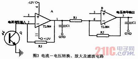
3 software part In order to facilitate program debugging and improve reliability, the program design uses a top-down, modular, structured programming approach. The program divided by task module mainly includes initialization program, main program, A/D conversion subroutine, data processing subroutine (including zero adjustment, judgment operation error, displacement value and Young's modulus value), LCD display. Programs, keyboard scan subroutines. The main flow chart of the system is shown in Fig. 4. The operation detection is to help remind the operator. If there is no mistake, the LCD display will show the corresponding data value of the function key. If the operation is wrong, the LCD display will show the word EOF. 
![]()
Where L = 100.00 cm, m = 3000 g, and g = 979.4 cm/s2. uF only takes a valid number and writes the result expression from the "last alignment" principle:
E=E±uE=(1.8±0.3)×1011(N/m2)
5 Conclusion This method can greatly simplify the original experimental device, improve the efficiency and accuracy of the experiment, and the cost is lower than the original. After the improvement, it not only retains the teaching content of the original experiment, but also helps students understand the structure, principle, characteristics, and usage methods of the photoelectric sensor, applies advanced scientific and technological achievements to the teaching experiment, and expands the students’ knowledge. The instrument will also be an example of the modernization of classic experimental teaching.
Measurement of Metal Young's Modulus Based on Photoelectric Sensors
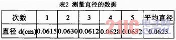
Abstract: This article presents a new method for the measurement of Young's Modulus of metal wires by using photoelectric sensors. The key to this measurement is the accurate measurement of the small length variation of the wire. Firstly, the photoelectric sensor converts the displacement change into the change of the current quantity. After the IV conversion, amplification and analog-to-digital conversion, the electrical signal is finally sent to the single-chip microcomputer for data processing. At the same time, the human-machine dialogue is realized through the keyboard and displayed on the display. As a result, intelligentization of the Young's modulus measurement is achieved. 2.1 Photoelectric Conversion Module A silicon photocell is a large-area photodiode, which is used to convert light energy incident on its surface into electrical energy. We know that when a silicon photocell converts light energy into electrical energy, the transformed current signal changes. A linear relationship with the change in incident light intensity. In order to verify the characteristics of the silicon photocell, we also carried out relevant measurements, and the measured data were fitted with MATLAB software to obtain a function that meets the least squares method. The functions obtained by different levels of fitting are as follows : 4 Data recording and processing After the experiment recording and data processing, we take the proportional coefficient of the displacement value and the converted and amplified voltage value as 44 and use it directly in the data processing subroutine to detect the elongation of the wire using this system. The measured data are shown in Table 1. The data of the diameter of the steel wire measured with a micrometer is shown in Table 2.