Frp Manhole Cover,Frp Cover,Frp Square Manhole Cover,Frp Manhole Cover With Frame HEBEI DONGDING CHEMICAL TRADE CO.,LTD , https://www.hebeiopct.com
I. INTRODUCTION Since the United States developed the first CNC machine tool in 1952, after more than 50 years of development, it has now spread over all industrial fields. With the increasing use of numerically-controlled machine tools in key positions and key processes, failure to repair them in time after a failure will cause great losses. Therefore, the maintenance of numerical control systems is becoming increasingly important and urgent.
Siemens AG is a manufacturer of CNC systems widely used in China. Its SINUMERIK 810D series and 840D series CNC systems are modular CNC control systems and are mainly used in flexible manufacturing systems. Its processing and application technology has unparalleled advantages, stable performance, simple operation, high cost performance, and is the first choice for users in many application fields.
II. Project introduction In recent years, Harbin Aviation Industry Group Dong'an Microfax Co., Ltd. has invested heavily in the purchase of a large number of CNC machine tools at home and abroad in order to increase the production capacity of new automobile engines. This article takes the example of the horizontal machining centers produced by four German CROSSH Chuaner (Heller-Joy) and the three vertical machining centers of Shenyang as examples to briefly explain the maintenance of the Siemens CNC system. The control system of the German horizontal machining center is SINUMERIK 840D from Germany's Siemens AG. The driving parts are SIMODRIVE611D, human-machine interface host unit PCU50, and operation panel OP012. The domestic vertical machining center adopts the SINUMERIK 810D CNC system, the driving part is also SIMODRIVE611D, the man-machine interface is MMC100.2, and the operating panel OP17. 
Third, maintenance instructions As the company's engine production gradually increased and the use of machine tools to increase the time, these seven processing centers have a variety of problems, combined with the actual fault, the Siemens CNC system and drive modules, etc. appear in accordance with the software, hardware , PLC/NC program and electromagnetic compatibility are elaborated!
1. Hardware Maintenance The hardware of the CNC system is mainly composed of three parts: power system, control system, and independent unit.
(1) Control power supply The control power supply is an important part of the hardware of the numerical control system, while the power supply part failure accounts for a certain proportion in the fault phenomenon.
Most of the DC power supply in the Siemens CNC system, as a control switch power supply. The voltage of the DC bus in the drive system is 600V, which is obtained through the servo transformer and the rectifying device. Because of its high voltage, the probability of damage is also high.
A Shenyang Zhongjie Machining Center OP17 has no display. After inspection, the 24V power supply module is damaged, and the output voltage is far from meeting the requirements. The new power supply module must be replaced.
In a German machining center, after the normal start-up, the alarm indicates that the driving part is not ready. It was discovered that the 611D power supply module was short-circuited and the DC bus voltage was 0. After inspection, it was found that the incoming line AC power was greater than 440V, breaking through the internal power supply module. Device caused. At this time, it is necessary to replace the power supply module and add an automatic voltage regulator to the external power supply.
(2) Control system The control system referred to here is the link between the unit and each unit involved in the signal generation, processing, transmission, and execution of the control device. According to the system manual analysis of electrical principles, a complex system is divided into a variety of functional blocks, and then each function block input and output signals are analyzed to find out the links between them.
A German machining center (840D system) with PCU50 with hard disk. Can not start the phenomenon, OP black screen. After checking, the hard disk was damaged. After the hard disk ordered by Siemens, the installation was completed. Because the version is different, the HMI file needs to be updated. The file is transferred to the new hard disk using the LAN network (RJ45 interface) and automatically installed after the restart. Normally, the GHOST program that comes with the hard disk is backed up to the laptop (it can be backed up to the local hard disk, or it can also be backed up to other computers. If you back up to another computer, you should pay attention to the partition of the hard disk is more than the partition of the local hard disk). .
The production tasks of Zhongjie machining center are heavy and the conditions on the site are relatively poor. When the 611D drive module ignition phenomenon occurs in the machining center and an alarm occurs, the drive module is inspected without problems, but the servo motor is found to be burned. The analysis needs to be replaced by replacing the motor. Because the relative encoder is used, the zero point does not need to be reset, and the zero point can work normally after power on. 
(3) Stand-alone unit The stand-alone unit refers to a part that can be combined with other parts of the CNC system with a simple adaptation, such as an external PLC, a grating measuring system, a tape reader, a pulse encoder, a rotation speed sensor, and operation. Panels and so on.
Zhongjie machining center had no response to the start button on the OP17. Checking the status of the PLC at this point did not respond. After checking, the button was damaged and the extra button was replaced. 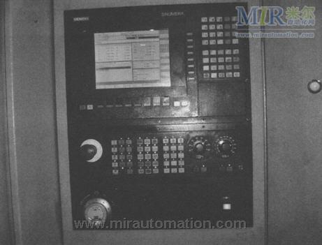
The German machining center uses closed-loop control of the 840D CNC system and is responsible for the precision machining of engine components. Positional deviation alarms occur during processing. Because it is a closed-loop control, it is first necessary to determine at which end of the encoder or scale the fault is. Firstly, the grating scale is shielded, only the encoder is used to detect, the alarm disappears, and the fault appears on the grating ruler. After careful inspection, the grating scale is stained and the cable is worn. After the cable is processed and replaced, the fault can be solved.
2. Control system hardware fault inspection and analysis After the above description, we can summarize some of the hardware inspection methods.
(1) Routine inspection 1) Appearance inspection After the system malfunctions, first perform a visual inspection to find obvious faults, and have targeted 2) Check the connecting cables and wiring for the fault location and check with the auxiliary equipment.
3) Inspection of connectors and connectors For faults, inspect the terminals and connectors to which they are associated as they tend to loosen, heat, and oxidize.
4) Checking the power supply voltage The power supply check is very important because the normal operation of the CNC system and the normal supply voltage are the basic guarantees.
(2) Panel display and indicator panel The display of fault information provided by the panel (OP) is very important. The self-diagnosis of the Siemens CNC system provides very rich alarm signals and help information. Carefully analyze them. The indicator on the panel or the LED on the circuit board indicates the general direction of the fault and provides us with some information about the fault, which can help find the location of the fault.
Zhongjie machining center, the panel displays the alarm prompt is the cooling pressure is low, after inspection is the cooling water pump damage, can not reach the system's rated pressure, causing pressure switch alarm. Visible, this information can remind maintenance personnel to quickly locate and check the fault site.
(3) Analytical method This is a method of finding faults and narrowing faults. Under the circumstance that the principle of the entire system is clear, the system is divided into functions according to functions, and it is judged which part has a problem according to the condition of the failure. 810D/840D can be divided into MMC/PCU, PLC, CCU/NCU, MCP, drive part, etc. Each part has its own different functions. It can judge the approximate location of the fault according to the alarm prompt and fault analysis, thus shortening the maintenance time.
3. Software maintenance The running process of CNC machine tools is the process of machine tools under software control. If the machine tool fails, you should check the software first, because this kind of stoppage is mostly caused by the software.
Siemens has a wide range of software, powerful functions, and good openness and is well received by users. This includes WINDOWS and DOS-based software that can be used in different environments. For example, WINCC is the host computer monitoring program, STEP7 is used for PLC programming, TOOLBOX is used for installation and debugging, PCIN and WINPCIN are used for transmission, HMI software and so on.
(1) NC machine tool data and PLC machine tool data These are the data that the machine tool's CNC system adapts to various aspects of the machine tool. Its meaning is extensive. You can understand the value range, standard value, and use value according to the instructions provided in the manual. According to the specific circumstances to give optimization. 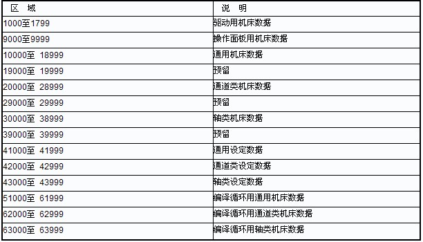

(2) NC program and PLC program NC machining program is to describe the machining process and the tool trajectory. The PLC program controls the logic of each input point and calculates the control logic according to the user logic, and then sends out corresponding control signals to each output point in sequence.
During the commissioning, Zhongjie machining center had the following failures: CYCLE85 fixed cycle (boring cycle) could not be executed. After inspection, neither GUD7 nor the cycle was loaded. The problem was solved after loading; the spindle positioning angle changed, and it could not be normal. Exchange tools, in the tool change program L6 to adjust the spindle positioning angle, that is SPOS=XXX. XX This sentence, according to the actual situation to modify; Dl / 0 module does not output, and no action on all the input signal PLC, because it is based on the standard PLC user program based on the actual situation of modification, doubt MD14512 [0l-[ 5] There is no correct setting. Observe in the PLC status window. If there is no setting, the problem can be solved after the corresponding settings are made.
4. Electromagnetic Compatibility General industrial production processes have harsh field conditions and can generate various types of interference and noise. Interference and noise are problems that cannot be ignored, especially for some precision equipment (such as numerical control equipment) that must be taken seriously. Interference may affect the programs and data in the CNC system, resulting in unnecessary alarms and interruptions. In severe cases, the machine will lose control and cause major accidents.
For Siemens systems, high-voltage, digital dynamic systems are used. Effects of digital and analog grounds; Electromagnetic wave interference, including on/off of electrical equipment (electric spark, high frequency power supply) near the system, passing vehicles, electromagnetic waves, etc.; fluctuations in power supply power supply, long-term voltage, overvoltage, etc. It has a certain influence. 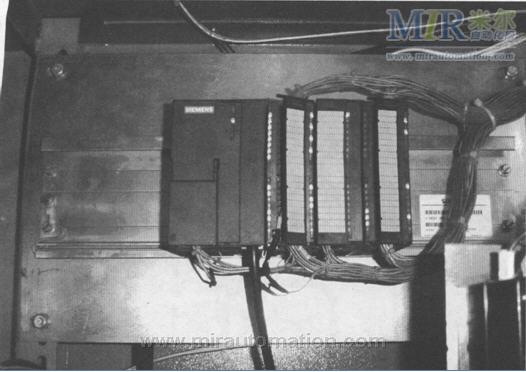
Therefore, the following aspects must be considered when debugging and maintaining CNC machine tools to avoid interference.
1) Good power system against interference.
2) Reasonable grounding method.
3) Scientific wiring.
4) Field environment that meets the requirements of anti-jamming.
5) Efficient software anti-jamming measures.
The third station of the Zhongjie machining center has recently been disturbed, causing some wrong actions and information. After careful inspection is ground wear, in addition to high harmonics caused by the grid into the ground, reconnect the ground, select the appropriate capacity of the power supply and isolation transformer, the phenomenon disappears!
IV. Concluding remarks In summary, only the experience of repairing the Siemens system is explained. China is a large manufacturing country. With the increasing number of CNC machine tools, it is believed that the flexibility and openness of Siemens products and high cost performance make more users consider it the first choice for CNC systems.
Siemens CNC system fault repair
Abstract: This article only takes SIEMENS SINUMERIK 810D/840D CNC system and its supporting SIMODRIVE611D drive module as an example to briefly explain the maintenance method of Siemens CNC system. The TH5940 vertical boring and milling center produced by Sino-Citizen Friendship Factory, in the process of tool change, operator misoperation, press RESET build, resulting in confusion knife number. This requires re-entering the tool number in the DB block to create a new tool table. This is because when the tool change is not completed, press the RESET key to reset the counter and the tool number count error.
Figure 1 NCU and 611D
The control section of Figure 2810D
Figure 30P and MCP
Siemens data classification table
Figure 4TC section
Figure 5 PLC section