Strong Roll Up,Standard Roll Up Stand,Mini Retractable Roll Up,Spring Roll Up Stand SUZHOU JH DISPLAY&EXHIBITION EQUIPMENT CO.,LTD , https://www.jh-posterstand.com
For example, the orifice flowmeter measures the flow rate, within the accuracy of the determined outflow coefficient, and requires symmetrical, non-vortex flow. In order to obtain the performance of the published flow measurement, the AGA 3 report recommends the minimum straight pipe length, pipe diameter change, and orifice plate flow meter upstream installation requirements. When the orifice plate flowmeter specification (β ratio) is increased, due to the reduced flow blockage, the effect of the orifice plate on the profile of the velocity profile is also reduced, and its sensitivity to fluid disturbances is also increased.
Turbine flowmeters also improve the flow profile due to the effect of the fluid on the rotor. Turbine flowmeter performance has also been improved due to improvements in the inlet flow profile. Due to the sensitivity of the turbine flowmeter to the asymmetry of the velocity profile, the report AGA 7 required turbine flowmeters to use rectifiers to eliminate the inlet flow vorticity.
Since the ultrasonic flowmeter basically has no obstacles affecting the flow of the population, the flowmeter does not change the flow profile. The flowmeter accurately determines the flow based on the flow sample obtained by the flowmeter according to a reliable calculation method.
In the design of multichannel ultrasonic flowmeters, manufacturers attempt to optimize the flowmeters to reduce their sensitivity to flow disturbances. If the meter can compensate for all flow disturbances, the rectifier can be eliminated. However, due to a small amount of published data on how the rectifiers affect the performance of multichannel ultrasonic flowmeters, there is still interest in the combined use of rectifiers and ultrasonic flowmeters. According to other types of flow meter application experience, the rectifier means potential benefits.
As a cost-effective alternative to multi-channel flowmeters, it makes sense to use rectifiers with inexpensive mono-ultrasonic flowmeters. In addition, a small amount of reliable test data confirms the performance of a mono flowmeter using a rectifier.
These results were obtained from the first part of the experiment, which attempted to determine the practical experience of using 8in mono and multichannel ultrasonic flowmeters with different piping installations and when used in conjunction with a rectifier. This test is to set up an elbow or two elbows upstream of the test flowmeter and run it with or without a rectifier.
Further tests are intended to evaluate the flow measurement accuracy of the bidirectional flowmeter when the measurement performance and flow are less than 1% of the flowmeter capacity. Where fluids can be two-way flow, such as underground gas storage facilities, people planning to install ultrasonic flow meters are concerned with bi-directional measurement performance.
For the installation of a metering station, the number and caliber of the meter need to be determined. Because of the range ratio, low-flow measurement performance should also be concerned.
Second, the test method Flowmeter installed in the test section of the high pressure loop (HPL), the test medium for the delivery of natural gas. At the same time, the data on the critical flow nozzle set on the ultrasonic flow meter and the HPL was collected and used as a flow rate standard.
Five double-weighted sonic nozzles were calibrated on-site relative to the HPL weigh tank system at different pressures. For all calibrations, gas properties were determined by an on-line gas chromatograph and AGA report state equation #8.
The static pressure associated with the HPL's reference pressure is measured at a double pipe diameter downstream of a flow meter. The gas temperature is measured at three pipe diameters downstream of each flowmeter. The measured temperature and pressure are used together with the measured gas composition and the gas volume measured by the ultrasonic flow meter to calculate the mass flow rate of the ultrasonic flow meter, which is then used to compare with the flow rate determined by the critical flow nozzle.
According to the manufacturer's choice of program, ultrasonic flow meters can use different methods to obtain volumetric flow. The internal calibration methods of the flow meters M3 and M4 are used to calculate the total gas volume and the time during operation. Then calculate the average flow based on the total amount.
The flow meters M1 and M2 report (measure) the actual flow rate, provide a flow rate once per second, and determine the average volumetric flow rate. Individual channel status, speed, and speed data are also recorded.
A typical test system consists of a recirculating gas that passes through the flow circuit and achieves a stable gas temperature and pressure. A combination of different sonic nozzles is selected and switched to determine a steady flow. A test point consists of the average of the traffic and other metrics calculated over the 90s period. One test point is repeated six times to calculate the mean and standard deviation. The measurement data is also collected by two turbine flow meters. Turbine flowmeter data confirmed the consistency of the experiment.
The four flow meters used in this test were supplied by the manufacturer and they are all commercially available. No flow calibration was performed before this project was tested. Four flow meters have two multichannel channels and two mono channels. Table 1 shows the flow channel channel layout. 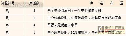
Third, the basic test Installation of the basic test of the pipeline installation is shown in Figure 1. All piping was made of an 8in ID No. 40 carbon steel tube (7.981in ID) and the internal weld was polished. The test flow meter was installed at 40D (D=8in), 59D, and 97D downstream of the 90° elbow. A 12in x 16in x 10in Sprenkle beam rectifier is installed upstream of the elbow, followed by a 10in x 8in concentric head and a 43d8in straight section until the elbow. Each flow meter can be tested in two of the four axial positions (see Table 2). 
For the flowmeter M1, at speeds greater than 10 ft/s, all data falls within 0.4%, regardless of speed (see Figure 2). At flow rates below 10 ft/s, the error curve is deflected upwards, which may be caused by a positive zero deviation or a deviation from the correction algorithm. This cannot be completely attributed to the difference in velocity profile at low flow, perhaps two The effects of the synthesis.
Check the zero flow of the flowmeter and indicate that the zero drift is 0.01ft/s. If zero drift is removed, the upward deflection will be flattened due to the minimum velocity point (2.8 ft/s) drifting to 0.35% and the point drifting to 0.18% at 5.6 ft/s. In any case, this does not mean that the upward deflection of the curve is entirely caused by the zero drift. 
The measurement error of the flowmeter M3 is related to the speed of flow through the flowmeter, as shown in FIG. The non-linear characteristics of this flowmeter measurement error are different from those observed in a similar experiment previously performed on the 12in flowmeter made by MRF (Grimly) and elsewhere (VanBloemendaal and VanderKam). Only when the flow meter is installed at 59D and the data collected at a pressure of 400 lb/in2(A), the average flow rate is still above 10 ft/s, the error falls within 0.3%. When the speed increases, the error curve is Tilt down. 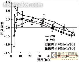
Data, including suspicious data sets, were kept within 0.5% error at speeds above 10 ft/s. These data also indicate differences in flow measurements when the pressure was increased from 400 lb/in2 (A) to 900 lb/in2 (A). It is 0.2%. When the flowmeter is compared between 59D and 97D, the difference in the actual result at a pressure of 900 lb/in2(A) is 0.1%.
A possible explanation for this difference is that the speed profile continues to develop after 59D. From the comparison of the single channel velocity ratios, it can be seen that the velocity profile shape is improved. Table 3 shows the ratio of the center channel velocity (ultrasound channel at the centerline of the pipeline axis) to the velocity of the external channel at the maximum flow point of the flowmeter M1. A similar calculated value of the flow meter M3 is shown in Table 4. Since the flowmeter has a unique channel position, comparisons should not be made for different flowmeter types. 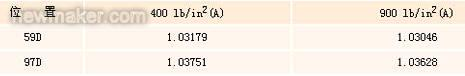

However, there is a consistent difference between the two flow meters in the test results of 59D and 97D. The smaller ratio of 59D test data indicates that the velocity profile at this location has a smaller arc than the velocity profile at 97D. The difference in responsiveness of the flow meter also has the result of a section sensitivity. The purpose of measuring the velocity profile is to better characterize the velocity profile under the baseline installation conditions.
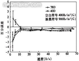
The mono flowmeter M2 (see Figure 4) has an offset of approximately -1.2% when mounted at 78D; there is an offset of approximately -1.8% at 40D, the results of this flowmeter indicate that in the flow measurement The error value is independent of the pressure but is related to the axial position. The test error curves of mono flowmeter M4 at two axial positions and two operating pressures are shown in FIG. The curve shows an average deviation of 0.5%, which also indicates that the on-line pressure has a greater influence on the measurement result than the distance between the 90° elbow and the flow meter. 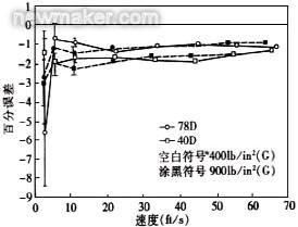
Fifth, the impact of the installation on the test The installation process of the impact test that has been implemented so far is shown in Figure 6. The mono flowmeter was tested in two different positions 1 and 2 (a single 90° long L-shaped bend downstream of 10D and 19D). The multi-channel flow meter was tested downstream of the elbows arranged in two planes and in positions 3 and 4 (downstream of the second L-shaped elbow at 10D and 19D). 
VI. Impact of Installation on Test Results These results are reported as deviations from the test results under the baseline conditions.
For the multi-channel flow meters M1 and M3, the data obtained when the flow meter is installed at 97 D downstream of the single 90° elbow represents the test results under the reference conditions. Mono flowmeters M2 and M4, the flow meter is installed at the downstream 78D of the 90° elbow, and the results obtained are used for the test results under the reference conditions. The test results under the baseline conditions are the ones that are closest to the optimum process installation.
The result of the multi-channel flow meter M1 testing at 10D downstream of the two planar elbows is shown in FIG. The test results show that the measurement error caused by bare tube installation is within 0.5% of the basic measurement results, and the relative error is on the order of 0.3% to 0.5%. The relative error occurs at high gas flow rates. The flowmeter was installed at 10D downstream of the second bend, and there was no significant difference in the test results with the 19-tube rectifier and the GFC rectifier. At speeds above 20 ft/s, the two rectifiers reduce the relative error by at least 0.25%.
For speeds below 20 ft/s, all results tend to converge, suggesting that the flowmeter is either sensitive to the velocity profile produced by the mounting arrangement or that there is no noticeable difference in the speed profile in this speed range. The determination of the planned velocity profile will help to explain these results, and it will further explain the data already collected on the ratio of single channel speeds.
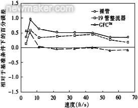
The test results of the flow meter M1 installed downstream of the two flat elbows 19D are shown in FIG. The relative measurement error of the results of the bare tube and the 19-tube bundle rectifier is approximately 0.5%. When the flow meter is installed at 19D downstream of the bend, the measurement error of the bare tube is slightly larger than the error at the flowmeter installed at 10D. Above 10 ft/s, the measurement results installed with the GFC are compared with the test results under the reference conditions. The comparison is within 0.1%. In addition, the measurement results converge at low flow rates. 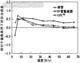
The results for the bare tube installation condition tested by flowmeter M3 mounted at 19D are shown in Figure 10, offset by about 0.2% compared to the flowmeter data for the 10D position, and remain above 20 ft/s. Within 0.25% of the basic test result. In addition to the highest flow rate, the 19-tube rectifier data is nearly identical. For airflow velocities above 45 ft/s, the GFC produces measurement errors that are closer to those of the 19-tube bundle rectifier and bare tube than under standard installation conditions. 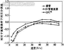

The results of the mono-channel flowmeters installed at the downstream of the 90° long bend at 10D and 19D are shown in FIG. 11 . The measurement results show that the error deviation is about 2% to 2.2% relative to the test error at the reference position of 78D downstream of the 90° elbow. An additional error offset of 1.3% results from a 90° rotation of the flowmeter about the axis. 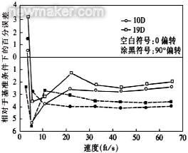

The flow meter M4 installed downstream of the elbow 19D has an offset of about 1.5% to 2% with respect to the reference condition except for the 90° position. The result is shown in FIG. 12 . Since the measurement channel should be 45° with the vertical direction, this measurement result shows that this flow meter is basically irrelevant to its position. In this case, although the axis center of the flow meter body is deflected, the position of the vocal tract remains consistent with the flow disturbance.
VII. CONCLUSIONS The test under the baseline conditions indicated that the fluid velocity profile at 59D downstream of a long-diameter 90° elbow was not fully developed and the flowmeter tested was sensitive to the subsequent development of the velocity profile. This shows that the accuracy of the tested 8in flowmeter can be improved by flow calibration.
The 8in multichannel flowmeter test results show that the use of a rectifier has the potential to improve measurement accuracy.
The monochannel flowmeter test shows that it has potential and can obtain better than 0.5% measurement accuracy under good flow field conditions. The flow meter's sensitivity to a simple spoiler is illustrated by testing of a flow meter mounted at a single 90° elbow downstream of 10D and 19D. Relative to the test under the reference conditions, the flow measurement error range is 1% to 4%.
The experimental test results are only preliminary for a large test plan. A more in-depth analysis of the obtained data and other test data from this test plan will yield a new understanding of the application performance of ultrasonic flowmeters in high-pressure natural gas.
Industrial Research Assessment of Ultrasonic Flowmeter Performance
Key words: Ultrasonic Flowmeter, Ultrasonic Pulse, Volumetric Flow I. INTRODUCTION Ultrasonic flowmeters derive gas volume flow by measuring the time the ultrasonic pulse travels in a fluid. For an ultrasonic flowmeter, the determination of flow accuracy is a function of the design and calculation method of the flowmeter and the upstream piping requirements, which is different from many traditional measurement methods. All flow meters are manufactured with a unified flange-to-flange size (31.5 in length) and an inside diameter (within 0.005 in) to facilitate the exchange of flowmeters in different mounting positions. Manufacturers provide parameters for mechanical, electronic, and other measured flowmeters based on dedicated programs. At the time of the test, the profile correction parameters used with the flowmeter were checked by the manufacturer. The special parameters concerning the test conditions (the fluid properties for the electronics inside the flow meter) are adjusted each time as required. Figure 7 Correlation of downstream 10D multiphase flowmeter M1 with two elbows 10D apart in the same plane Figure 10 Figure 7 Multi-phase flowmeter M3 downstream of two elbows with a distance of 10D in the same plane. The performance of the multi-phase flowmeter M3 shown in Figures 7 to 10 shows that there are benefits to using a rectifier for a multichannel ultrasonic flowmeter. It depends on the type and location of the flow meter. Some of the above cases cause such absolute errors relative to the test error offset under the reference conditions. These absolute errors are actually closer to zero error than the results under the reference conditions. Whether this result is caused by an accident or due to an imperfect velocity profile in the flowmeter study is unclear.
Table 1 Test flow meter geometry
Table 2 Test position of the flowmeter under reference conditions
Figure 1 Basic flow test pipeline installation
The complete test plan for each flow meter requires testing at four locations. When the flowmeter is moved from one axial installation position to another, the upstream and downstream straight sections (10D and 5D, respectively) should be removed integrally with the flowmeter to center the flanges upstream and downstream of the flowmeter. . Pressure and temperature transmitters associated with each flowmeter should also remain on the original straight pipe section in order to reduce additional errors when the flowmeter changes position.
IV. Basic Test Results The test performance of two multi-channel flow meters (M1 and M3) under the reference installation conditions is shown in Figure 2 and Figure 3. The results are expressed as percent error (relative to the MRFHPL critical flow nozzle) as a function of the average flow rate through the flow meter. One point represents the average of 6 repeated measurements for each flow, and the error band represents 95% confidence level. Figure 2 Basic flow measurement results for multichannel flowmeter M1
Examining the flow calibration curve shows a difference of about 0.2% between the meter installed at 97D and the error measured at 59D. The error at 97D is greater than the error at 59D (more negative). Similar measurement errors are also present in the 400 lb/in2 (A) and 900 lb/in2 (A) test cases. Figure 3 Basic measurement results of multichannel flowmeter M3
In the 59D, 400 lb/in2(A) data set, individual channel status information indicates that this is because the measured propagation time cannot pass the internal consistency check. This may be the reason for deviations from other data sets. Table 3 Center-to-outer speed of M1
Table 4 Speed ​​Ratio of M3 Center Channel to External Channel
Figure 4 Basic measurement results of mono flowmeter M2
Figure 5 Basic flow measurement results for mono flowmeter M4
The error curve shows inaccuracies in the data at 400 lb/in2(A), 78D, and other results at speeds below 10 ft/s. In general, the measurement data of a mono flow meter is more decentralized than the data measured by a multi-channel flow meter. Since such a flow meter does not have the advantage of an average airflow of a multi-channel ultrasonic flow meter, this dispersion is not surprising. This characteristic of mono flowmeters is particularly evident at flow rates below 10 ft/s. Figure 6 Pipeline layout for upstream flow impact test
The test pipeline is bare and two different beam rectifiers are installed upstream of positions 3 and 4. The first flowmeter is located 5D downstream of the rectifier outlet, which is consistent with the minimum requirements for turbine flowmeter installations reported in AGA7. In addition, in the multi-channel flowmeter test, the arrangement of the two flat elbows is arranged in a horizontal direction with the pipeline. Since this arrangement represents an installation in which the elbow provides a vertical offset, the flowmeter is rotated 90° to maintain its relative correct orientation of the measurement channels and flow disturbances. Figure 8: Relevant performance of multiphase flowmeter M1 downstream 19D of two elbows with 10D distance in the same plane
The test results of the multichannel flowmeter M3 installed downstream of the double bend (see Figure 9) show that for bare tubes, the M3 error is less than 0.25% for speeds greater than 20 ft/s. 19 Tube Rectifier and GFC Rectifier Results Bare tube measurements were included with a difference of -0.30% to 25%. The relative error as a function of the flow velocity is caused by the arc of the test data (see Figure 3) under reference conditions at 97D, 400 lb/in2(A). Figure 9 Figure 7 Relevant performance of multiphase flowmeter M3 downstream of 10D two elbows in the same plane
Fig. 11 Related performance of a single 90° elbow downstream mono flowmeter M2
Figure 12 The relative performance of a single 90° elbow downstream mono flowmeter M4
Because in this example, the mono flow meter is mounted in its normal orientation, its vocal tract is 30° from the vertical, which is probably related to the mounting orientation of the flow meter. In this installation, the main asymmetric component of the flow is in the vertical plane, and when the flow meter is rotated 90°, the orientation of the channel relative to the flow disturbance changes.