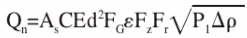
introduction With the rapid development of natural gas in China, natural gas flow meters with very high accuracy are needed. At present, most natural gas companies in China use natural gas flow measurement instruments as orifice flowmeters, which have the advantages of simple structure, low cost, and high measurement accuracy. According to relevant data, more than 95 percent of oil and gas companies use orifice flow meters on trade meters. The orifice flowmeter is a kind of testing instrument that detects the pressure difference between the two sides of the concentric orifice plate installed in the pipeline to obtain the flow data. It is mainly composed of a throttling device, a differential pressure gauge, a pressure gauge and a thermometer. It is designed and manufactured based on the principles of conservation of energy and flow continuity equations. Its method of calculating the natural gas flow rate is to generate a pressure difference through a throttling device. Then some instruments are used to measure the pressure difference, pressure, and temperature. Finally, data is obtained using a flow totalizer or a computer control system. 1 orifice plate flow meter working principle and characteristics The orifice plate flow meter is based on the principle of conservation of energy and flow continuity equation. The calculation method is based on the pressure difference between the two sides of the concentric orifice plate installed in the pipeline. The structure is measured by a thermometer, a pressure gauge, and throttling. Equipment and other components. Because of its low cost, simple structure, high measurement accuracy, and suitable for engineering measurement and trade with low precision requirements. China has been using orifice flowmeters for a long period of time, and has a very sophisticated orifice flowmeter design, production, processing experience, and its orifice flowmeters can also measure natural gas flow in some unknown range. At present, China's mainstream natural gas measuring instruments are orifice flowmeters. 2 Natural gas flow calculation method 2.1 Basic Formula for Calculation of Natural Gas Volume Flow Where Qn———natural gas volume flow under standard conditions, m3/s; C———outflow coefficient; β——— diameter ratio; ε———expansion coefficient; d———hole plate opening diameter, mm; Δp - pressure difference before and after the throttle, Pa; Ρ1—density of natural gas in upstream conditions, kg/m3; Ρn—the density of natural gas in the standard state, kg/m3. 2.2 Practical Formula for Natural Gas Volume Flow Calculation In the formula, the As———second measurement coefficient depends on the unit of measurement. This type of As=3.1794×10⁻⁶; E———asymptotic velocity coefficient; FG————relative density coefficient; Fz --- super-compression factor; Fr———flow temperature coefficient; P1————Absolute static pressure of pressure hole in orifice plate, MPa. 3 orifice plate flow metering error analysis 3.1 Effect of Outflow Coefficient C on Measurement Accuracy The calibration of the orifice flowmeter is related to the outflow coefficient. It needs to reach a sufficient length in the upstream straight section, and its throttling device needs to reach the necessary technical requirements. The flow coefficient is also related to the Reynolds number and changes with it. When the value of c increases, the Reynolds number decreases, whereas if the value of c decreases, the Reynolds number increases. The flow coefficient C will also change with the flow rate, and its change will decrease with the increase of the flow rate. When the actual flow rate is smaller than the scale flow rate, the flow error caused by it will increase. At the same time, the C value is a variable, which changes according to the Reynolds number change. When the Reynolds number reaches a certain value, the change amount will become smaller. With respect to flange pressure, the Reynolds number exceeds 106 and the transfer pressure has to exceed 210. 3.2 Uncertainty factors of actual physical properties of measured medium (1) The influence of the relative density of natural gas on flow metering. The natural gas flow rate will change with the change of 1/Gr. The relationship between the two is a proportional relationship, which can be seen from the above equation (2). If Gr is considered as a separate quantity, then when the uncertainty of Gr is plus or minus 0.5%, this is the natural gas standard volume flow with an uncertainty of plus or minus 0.25%, so it is obvious Flow measurement will be affected by the actual relative density of natural gas. The cause of Gr uncertainty is due to the lack of measurement and analysis as well as the determination of the relevant physical parameters of real natural gas. For example, the degree of deviation of the actual air composition from the standard components, and the uncertainty of the measurement of the molecular weights of the respective components. At present, there are two ways to confirm Gr, the first is to use buoyancy gas balance, momentum specific gravity meter and other instruments to detect the actual relative density; the second is to use gas analysis instruments, first learn all the components of natural gas, and then calculated according to the Cr value. Now our country usually uses the latter method. But because of the difference in pressure and temperature, Gr is a variable. This requires the use of on-line chromatography to observe changes and further increase the accuracy of the measurement. (2) The effect of natural gas compression factor on flow metering. The result of flow measurement usually shows flow out during actual operation, but because the actual conditions of different projects are different, the standard gas flow is generally considered at this time. When we encounter the influence of external factors (no high pressure, high temperature), we can use the ideal gas equation until the volume flow. However, there are differences between reality and ideal, and the same real gas is also different from the ideal gas. Especially when the pipeline pressure is large and the temperature difference is large, the ideal gas state equation is not applicable here. There are three ways to calculate the compression coefficient of natural gas. The first method is to use the Katz curve method. The advantage is that the solution method is fast and easy to use, but its disadvantage is that the error is large. The second method is to use the Katz table method, but its disadvantage is that the algorithm is cumbersome. When there is no relevant compression factor, interpolation method is also used, but the advantage is that the calculated value is the most accurate. The third type is to consult the "Quick Manual of Compression Factors for Natural Gas". (3) The effect of the coefficient of expansion ε on the flow rate. We need to add a correction factor, ε, to the change in the effect of the density of the gas as it passes through the orifice. This introduced coefficient makes us a major cause of error in actual work. If the flow of natural gas at work does not reach the expected level, the true correction factor ε will be much smaller than the planned ε. Finally, the resulting data from work is much smaller than the expected data. Assuming that the true correction coefficient is larger than the correction coefficient in the work, the final result is also much larger than the actual result. (4) The effect of pulsating flow on the flow measurement. The root cause of the pulsatile flow is because the speed of gas flow in the instrument pipeline and the pressure of the gas are changed. This change can lead to changes in the pressure difference, so that the lines recorded by our instrument are not a single line. It's a broadband. However, there are only a few reasons for this pulsating flow, while others are combined for many reasons. Such as the accumulation of residual liquid in our long-distance pipelines, the use of compressed natural gas instruments, and the perturbation of pressure in natural gas fields, natural gas users cannot use natural gas on average. The ability to have a steady flow of traffic is the most fundamental factor in the calculation of the flow rate by the retention device. When we need to measure the fluctuation of the unit, we cannot measure it well, which will increase the measurement error. Therefore, in order to make our final measurement error small, it is necessary to weaken the pulsating flow. 3.3 Instrument Design, Installation Management Error Analysis (1) Design error of the instrument The reason for poor instrumental error is because of the inadequacy of the instrument design or because of unpredictable changes in the instrument's use. This kind of error is mainly manifested in the following aspects: The first is because the sharpness of the top angle of the instrument aperture plate has not reached the expected standard, the parameters of the instrument tube hole are not calculated according to the calculation, and the height of the instrument control panel cannot reach Work standards, or the work itself is not carried out in accordance with the prescribed process, resulting in many irreversible errors in the work, eventually leading to error. (2) Installation and management errors Then this error will eventually develop into a source of persistent errors that cannot be accurately determined. There is a strong commonality in this error. For example, during construction, the construction materials that meet the requirements are not enough. The material parameters of the construction cannot meet the parameters required for the construction. These parameters are embodied in the length of the material, the manufacturing process of the material, the deformation of the material orifice, and the redundancy in the material. The image of the material itself caused by the remaining material, the material Reynolds parameters can not meet the requirements for manufacturing, the location of the material welding deviation. The main errors in management are: the working instrument is not the instrument we need, the diameter of the orifice cannot pass the corresponding flow rate, errors occur in the connection parts of the impulse tube, the balance valve, and the differential pressure gauge, and the operator's own operation generates an error. . 3.4 Effect of Improper Flow Accumulation Method on Measurement The common orifice plate throttling device we use at this stage uses a different data calculation method than the secondary measurement tool which is different from its deconstruction. We need to use well-conformed orifice flow tools to calculate the flow of natural gas, and its data is inextricably linked to all aspects of natural gas. Assuming that the flow measurement system we use does not conform to the corresponding configuration tool, it will not be able to perform accurate calculations at work, which will increase the error of the instrument. Influencing factors of accurate metering in the operation of 4 orifice plate flowmeters At this stage, the flow statistics tables of our instrument maintenance boards often have some problems after long-term use: (1) We use the most basic orifice measurement instrument, one that can measure the limited range, the accuracy of the measurement is not high, and the environmental factors of the measurement body have a great influence, we need to use different orifice plate originals. (2) In some special times, our natural gas contains many impurities, so that the purity of natural gas cannot be improved. This can cause the metering equipment to be blocked, resulting in some errors that can actually be avoided. (3) Because natural gas and natural gas liquids are not well separated at this stage, the pressure and the pressure calculations in the pipeline for deriving the pressure will generate excess water and oil due to positive pressure and negative pressure. This will cause the differential pressure gauge to have Excess liquids are not calculated accurately. (4) Orifice plates need to be inspected once every other time, and they need to be washed and measured in routine parameters. However, the working conditions of natural gas meters are not good, and they cannot be checked and maintained at regular intervals. (5) When the pressure and temperature of the medium are changed differently, the volume of natural gas will follow this change, which will make the gas meter error. 5 measures to improve the accuracy of orifice flowmeter measurement We start with the reasons for measuring the error in natural gas production and study several different ways to reduce the error in different periods of natural gas measurement. 5.1 orifice plate flowmeter design and installation should strictly meet the technical standards Our orifice plate throttling device at this stage should be consistent with all the specifications of the regulation (SY/T6143-1996), especially when it is actually installed, it must match the corresponding parameters with the response parameters, in most cases All need at least the first 30D. 5.2 Elimination of pulsatile flow (1) Use wind-blown, sweeping, clearing the pipeline or using a liquid separator in a low place to reduce excess liquid in the pipeline. (2) We need to make the inner diameter of the measuring pipe effective under the condition that my measuring capacity can be achieved, so that the differential pressure and the aperture ratio can be improved. (3) In actual work, we should use the short lead pressure pipeline as much as possible. The purpose of this is to allow the drag in the pipeline to be pulled, but also to make the upstream and downstream pipelines have the same length. In this way, the resonance and pressure pulsation amplitude in the working system can be reduced in practical work. (4) We need to add a pressure-adjusting valve in front of the measuring point so that the pressure can be output smoothly. Adding a buffer tank in front of the measuring tube to store and release the gas can also serve as an effective error. (5) Control the metering valve downflow valve. High Torque Precision Winding Machine Semi automatic
According to the winding mode, it can be divided into flat winding machine, ring winding machine, flying fork winding machine and rectangular enclosed winding machine.
Leveling machine
Three dimensional High Torque Precision Winding Machine, Precision Winding Machine, Precision Winding Machinery for coil SUZHOU DEGU MACHINERY CO.,LTD , https://www.deguwindingmachine.com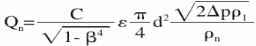 (1)
(1)  (2)
(2)
It is the most widely used winding machine in China, which can only realize automatic line arrangement, and all the remaining operations need to be completed by operators. Usually, the number of shafts is small to match the operation time of operators, and it is convenient to replace different molds to produce different products.
Advantages: cheap price, some mechanical processes can be completed manually, equipment deviation can be adjusted by operators to compensate, and product replacement is convenient.
Disadvantages: there are many labor needed, and employees need certain training, and are limited by the operator's operating proficiency.
It is suitable for low cost production, new product production, and a variety of types and small batch production.
A winding machine in which the wire is arranged in a spiral line on the outer layer of a work piece by rotating the main shaft and moving and positioning in three dimensions. It is usually used to process most transformers, inductors and all kinds of coils. It is the most widely used winding machine.
Ring type
Through the rotation of the main shaft (wire storage wheel) and the action of the auxiliary wheel, the wire is arranged in the form of helix ring on a closed ring, closed square or other similar workpiece. It is usually used to process closed coil.
Flying fork
It is a winding machine that drives the flying fork to wind by the side motor. It is usually used for winding process of cross instrument coil and rotor.
In order to adapt to the special winding mode of special products, the winding machine is produced. It is usually used for winding of stator and special products