Concrete Pump Rubber Seal include the concrete pump rubber gasket and rubber seal, also have natural rubber and polyurethane material, sizes are DN50-DN150, also include the concrete mobile boom placer rubber seal assy, every one boom rubber seals , we have the original one and one seals made in china, price is different, also the quality is different ! Concrete Pump Rubber Seal Ring Concrete Pump Rubber Gsaket,Concrete Pump Rubber Ring,Concrete Pump Pu Gasket,Concrete Pump Lip Gasket Hebei Shengdebaolong International Trading Co.,ltd , https://www.sdblpumpparts.com
With the rapid growth of the global population and rapid industrial development, the global water resources situation has deteriorated rapidly and the “water crisis†has become increasingly serious. In response to this situation, the Chinese government will invest 300 billion yuan during the “Eleventh Five-Year Plan†period to build or rebuild thousands of sewage treatment plants to promote urban sewage treatment and utilization, and reduce pollution. Under such a background, Huangshan City, Anhui Province, is investing in the construction of a sewage treatment plant. Currently, a 15,000m3 daily sewage treatment first-phase project has been completed, which is responsible for the important tasks of purification of domestic and industrial wastewater, improving the environmental quality of water bodies, and making Huangshan City the Become a beautiful city.
Before 2004, there were basically no large-scale centralized sewage treatment plants and other facilities in Huangshan City, not to mention flowmeters used for sewage flow detection. In the sewage treatment process, the flow of raw sewage is a key parameter to be tested. Since the original sewage is a medium containing particles, suspended solids, solid-liquid mixture, and corrosive medium, the most important feature of the electromagnetic flowmeter is that it can measure the flow of acid, alkali, salt solution, and solid particles (such as mud) or fiber liquids. Therefore, The sewage treatment plant uses two electromagnetic flowmeters to measure the flow of raw sewage.
1ã€Working principle of electromagnetic flowmeter
The basic principle of the electromagnetic flowmeter is Faraday's law of electromagnetic induction. When the conductor cuts magnetic force in a magnetic field, the induced electromotive force E at both ends is:
(1)
In the formula, K is the instrument constant; B is the magnetic induction intensity (T); v is the conductor movement average velocity m/s; D is the pipe internal diameter (m). 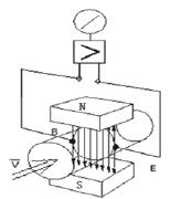
Figure 1 working principle of the electromagnetic flowmeter electromagnetic flowmeter working principle and structure shown in Figure 1, by the flow sensor and the converter of two major components.
When measuring the flow rate, the conductive liquid corresponds to the conductive metal rod in the Faraday test and flows at an average velocity v through the magnetic field perpendicular to the flow direction. The flow of conductive liquid induces a voltage on the measuring electrode that is proportional to the average flow velocity. The induced voltage signal E is detected by one or more pairs of electrodes in direct contact with the liquid.
According to the fluid volume flow formula is (2)
By formula (2) we can see that Q and v are directly proportional to a one-to-one corresponding function, then E and Q are also proportional to a one-to-one correspondence function, measured the induced voltage E, that is, measured the volumetric flow Q of the medium.
The measured inductive voltage E is sent from the cable to the converter, which is processed intelligently and then displayed on the LCD, or converted into a standard signal 4 to 20 mA output.
2, electromagnetic flowmeter features
(1) There is no resistance element in the measurement pipeline, there is no additional pressure loss, and jamming is not easy to occur, which has significant energy-saving significance;
(2) There are no moving parts in the measuring pipe, so it is not easy to wear, so the sensor has a long service life;
(3) The straight pipe section required by the sensor is short and easy to install;
(4) Reasonable choice of electrodes and lining materials, resistant to corrosion and abrasion;
(5) Bi-directional measurement system that can measure forward and reverse flow;
(6) The flow rate is measured as volumetric flow and is not affected by changes in flow density, viscosity, temperature, pressure, and conductivity;
(7) The sensor-induced voltage signal has a linear relationship with the average flow velocity, with a high measurement accuracy (±0.3 to -0.5%) and a wide range ratio (1:150).
3, electromagnetic flowmeter selection
Instrument selection is very important, the relevant information shows that the instrument in actual application has 2/3 of the failure is caused by instrument selection error or improper use, therefore, after the determination of the use of electromagnetic flowmeter, it should also be based on different processes, Environment, measurement, media and other comprehensive considerations.
3.1 Diameter selection According to the process pipeline diameter, pipeline pressure and sewage flow rate provided by the sewage treatment plant, the electromagnetic flowmeter with the caliber D=600mm is selected, and there is no need to shrink or expand the pipe on site.
3.2 Lining, Electrode Material Selection Electromagnetic flowmeters are mainly used to measure fluid flow with conductivity ≥5μS/cm. They should be selected according to the characteristics of the corrosivity, wearability, temperature and condensability of the tested substances and the price bearing capacity. Lining, electrode material.
Electromagnetic flowmeter lining materials are: Corrosion resistance, general resistance to low concentrations of acid, alkali, salt neoprene materials, wear resistance and corrosion resistance of polyurethane rubber, corrosion resistance And suitable for high temperature polytetrafluoroethylene, chemical properties equivalent to PTFE tensile, compressive FEP, resistant to dilute acid, alkali, salt temperature <60 °C polyethylene and temperature <100 °C polyphenylene sulfide and so on.
The electrode material is mounted on the inner wall of the pipe and is in direct contact with the measured substance, so it should be selected according to the corrosivity of the measured substance. Electromagnetic flowmeter electrodes include: (Ti) electrodes that are resistant to salt and less than 50% concentrated alkali solution, tantalum (Ta) electrodes that are resistant to acids and salts, noble metal platinum electrodes that are resistant to corrosion, and Hastelloy C that is not suitable for hydrochloric acid. Electrodes and Hastelloy B electrodes not suitable for nitric acid, stainless steel 316L with low corrosion resistance but low cost.
According to the main treatment of domestic waste water and industrial waste water, the sewage treatment plant, and then consider the price acceptable to the user, use neoprene rubber lining and stainless steel 316L material electrode.
3.3 Selection of protection level According to national standards, the sensor has two protection grades: IP65 water spray type and IP68 submersible type. According to the user's actual installation location in the low well, the sensor chooses IP68 dustproof submersible type.
3.4 Selection of Additional Functions (1) For the selected basic model, the electromagnetic flowmeter has an LCD display, 4 ~ 20mA current output and 0 ~ 1KHz frequency output. According to the flowmeter and computer communication requirements, need to increase RS-485 communication Mouth function,
(2) For sensors installed below ground, split type should be selected.
4, electromagnetic flowmeter installation and commissioning
4.1 Installation method (1) Installation point selection After confirming the flow direction of the measured substance at the lowest point of the pipeline, the installation point must be selected to fill the measurement catheter at any time. This prevents the measurement catheter from being in the zero position due to lack of fluid in the measurement catheter. The resulting error is shown in Figure 2. 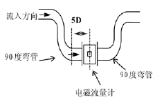
(2) Straight section guarantee 3D after the first 5D
In order to obtain the measurement accuracy of the meter, the length of the straight pipe on the upstream side of the sensor is not less than 5D, and the downstream side is not less than 3D (D is the nominal diameter of the sensor). If there are more than two elbows or other spoilers on the upstream side of the sensor, the forward straight section should be greater than 10D.
(3) When the signal electrode is installed horizontally horizontally, the axis of the electrode should be parallel to the horizon, because the electrode at the bottom is easily covered with precipitates, and the occasional bubbles in the measured medium wipe over the surface of the electrode, causing the output signal to fluctuate.
(4) Try to avoid vibration sources and magnetic sources (high-power motors, transformers)
Since the electromagnetic flowmeter has a small measured voltage and a low voltage, it is susceptible to external electromagnetic noise. Therefore, a reliable grounding (span) connection should be made during installation. Metal pipeline electromagnetic flowmeter ground connection (cross) connection method shown in Figure 3. 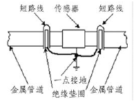
4.2 Converter Installation and Debugging The integrated electromagnetic flowmeter does not have a separate converter. The split converter is installed near the sensor or in the instrument room. The choice of location is larger and the environmental conditions are better. The distance between the transducer and the sensor is limited by the conductivity of the measured medium and the signal cable type, ie the distributed capacitance of the cable, the cross-section of the wire and the number of shields, and the signal cable (or model number) attached to the manufacturer's instrument. When the conductivity is low and the transmission distance is long, use a two-layer shielded cable.
In order to avoid interference signals, the signal cable must pass through the ground protection pipe separately, and the signal cable and the power cable cannot be installed in the same steel pipe.
During functional debugging, the smart converter performs parameter reading, critical value alarm testing, etc. on the meter, and then writes the flow coefficient value.
5, the instrument put into operation and troubleshooting
Before the electromagnetic flowmeter is put into operation, pipelines and flowmeters shall be thoroughly inspected, including the cleaning of pipeline debris, etc., and the electrodes shall be dried. It also includes the inspection of the electrical circuit. First, the grounding of the line should be checked. After the grounding is ensured, the insulation resistance and the grounding resistance test are also required.
The electromagnetic flowmeter was normally put into operation for more than a year, but basically no failures occurred. However, after one year, there was an abnormality in the performance of the electromagnetic flowmeter, in which the measured value became larger or smaller, or was constantly fluctuating, and after on-site inspection, The possibility that the pipeline is not full of pipes, media containing gas, etc. has been ruled out, and the occurrence of such problems may have been related to the failure of the cable line. Because the flow meter is buried underground with the pipeline, the sensor has IP68 protection structure, the converter is installed in the instrument box or indoors, the two are connected by cables, due to ground subsidence, the mountain environment is humid and other field conditions change, sensors and converters are not complete Doing moisture-proof (waterproof) treatment at the cable joints happens to be in a humid environment, such as instrument wells, cable trenches, etc., and moisture intrudes into the cable connectors, all of which may cause the following:
(1) The insulation of the signal line to the ground decreases, causing signal attenuation, and eventually the measurement result is too small;
(2) The contact resistance at the connection point of the signal cable becomes larger, so that the measured value becomes smaller. If the contact resistance is not stable, the measured value cannot be stabilized and interference can be easily introduced.
(3) The insulation of the excitation coil is reduced to ground, resulting in a small measurement result;
(4) The insulation performance of the signal line excitation line to ground is degraded, making the measurement result much larger than normal data. If this type of interference is unstable, the influence on the instrument will change, and then fluctuations will occur.
(5) The contact resistance of the excitation circuit cable connection becomes larger, the excitation circuit of the converter is in the non-constant current working region, and the excitation current is decreased, which also causes the measurement result to be too small. If the contact resistance is unstable, the measurement value fluctuates.
Judging this kind of abnormal situation, because it occurs in the signal circuit, it is judged to have a certain degree of difficulty, only in-depth site, in the exclusion of flowmeter other possible faults, it should check whether there is a problem with the cable, on-site maintenance personnel as long as the field excitation circuit resistance Measured values ​​are compared with the data provided by the manufacturer, test the grounding resistance, gradually determine the problem, and then take measures, or replace the entire cable, or keep the cable joints dry.
6. Concluding remarks Since the operating environment of the electromagnetic flowmeter is relatively complex and there are many factors that affect its normal operation, the debugging technology needs to be continuously summarized and updated. In short, if we properly select and properly install the electromagnetic flowmeter and take effective measures to maintain it, we can avoid or reduce the occurrence of failures, extend the service life of the instrument, and provide accurate and reliable measurement data for production.
In the modern sewage treatment process, equipped with flow detection instruments, constitutes a reliable automatic control system, so that the sewage water quality meets the conventional emission standards for the benefit of mankind.
Application of electromagnetic flowmeter in sewage treatment plant
introduction
Figure 2 electromagnetic flowmeter installation
Figure 3 electromagnetic flowmeter grounding