Heilongjiang Electric Power Lu summarized the application of waste heat power generation technology in cement plant in China Hu Zhongyu, Li Wen, Tang Yanchun Tang Jinquan 2 (1. Harbin Boiler Factory Co., Ltd., Harbin 150040, Heilongjiang; 2. Tianjin Cement Industry Design and Research Institute, Tianjin 300400) The characteristics of several generations of waste heat power generation systems and their application in China and the future development direction of waste heat utilization in China. 0 Introduction In the 1930s, Japan built more than 10 dry-process hollow rotary kiln (also known as hollow waste heat power generation kiln) with waste heat power generation system in North China and Northeast China. These waste heat power generation systems developed their own waste heat in China. Power generation technology and equipment laid the technical foundation. Due to the war, these cement kilns and waste heat power generation systems were basically in a state of suspension after construction. In the 1950s and early 1980s, more than a dozen cement kilns and waste heat power generation systems resumed production operations. By the late 1970s, due to the need to transform these dozen cement kilns and waste heat power generation systems, China began to develop its own technology and equipment for cement kilns and waste heat power generation systems. At present, China's own waste heat power generation technology and equipment have begun to take shape, aiming at the domestic market while targeting the international market. The development of China's waste heat power generation technology can be divided into the following stages. 1 The waste heat power generation technology and equipment of the hollow waste heat power generation kiln hollow waste heat power generation kiln has three generations. 1. First-generation technology - Japan's self-built hollow waste heat power generation kiln waste heat power generation system in North China and Northeast China in the 1930s and the early 1970s and early 1980s (see). Fund Project: National “Eighth Five-Year†Science and Technology Key Scientific and Technological Project (996) In the first generation technology, the cement kiln output is less than 500t/d, the cement clinker heat consumption is 6688~7524/kg, and the single cement kiln waste heat generation capacity Both are less than 3 000 kW, the main steam parameters of power generation: pressure <2.45 MPa temperature <400 cement clinker waste heat power generation is more than 90 heat boilers are horizontal boilers with imported exhaust gas temperature of 500 ~ 900 °C, and the steam turbine is a single inlet steam turbine. By the end of the 20th century, there were still nearly 60 such hollow waste heat power generation kiln in operation in China. 1.2 Second-generation technology - China's hollow waste heat power generation kiln waste heat power generation system developed on the basis of the first generation technology (see). In the second generation technology, the output of cement kiln is increased to 700t/d. The heat consumption of cement clinker is 6 061~6688k/kg. The heat recovery capacity of single cement kiln is increased to 4000~6000kW. The main steam parameters of power generation are: pressure 3.82MPa, temperature 450. Q cement clinker waste heat power generation is 150~17014 boundary 4, waste heat boiler is horizontal or vertical boiler with imported exhaust gas temperature 500~900C, and steam turbine has built about 20 such production lines for single steam inlet type. The technology of the hollow waste heat power generation kiln, the production of cement can no longer purchase electricity and all are powered by the waste heat power generation system. 1.3 Third-generation technology - China's hollow waste heat power generation kiln waste heat power generation system (see) combined with pre-decomposition kiln waste heat power generation technology and equipment. In the third generation technology, the output of cement kiln is still 700t/d. The heat consumption of cement clinker is still maintained at 6061~6688k/kg. The residual heat power generation capacity of single cement kiln is increased to 4: main steam pressure 3.82MPa, temperature 450 auxiliary steam The pressure is 0.2~0.5MPa and the temperature is saturated temperature plus 50C superheat. The waste heat power generation of cement clinker is 180 h/t, and the waste heat boilers are two boilers: one is the vertical exhaust gas temperature of 500~900C; the other is the vertical or horizontal boiler with imported exhaust gas temperature of 180~300C. The steam turbine is a steam inlet with two or three pressure levels. Heilongjiang Power's two production lines, the comprehensive energy consumption (clinker heat consumption plus cement power consumption) of the dry hollow rotary kiln using this technology has been the same as that of the pre-calcining kiln of the same scale (with four or five preheaters) . 2 Pre-decomposition kiln China began to develop pre-decomposition kiln waste heat power generation system and equipment in the late 1980s. By the end of the 20th century, it had 11 cement plants in China (a total of 19 kiln, single kiln cement clinker production 700 ~ 40 (1) t / d The total clinker production is 35 800t/d. 16 sets of waste heat power generation systems have been put into operation. A total of 16 steam turbine generator sets, the power generation capacity of a single unit is 2 400~12000kW, and the total installed capacity is 147.480MW. The total number of waste heat boilers in the waste heat power generation system is 38, the temperature of the boiler inlet exhaust gas is 180~450, and 11 sets of supplementary combustion boilers with fuels such as coal gangue are used as fuel, that is, in 16 sets of waste heat power generation systems, with supplementary combustion. There are 11 sets of boilers and 5 sets without supplementary combustion boilers. There are two types in the above-mentioned precalcining kiln waste heat power generation technology and equipment: one is a waste heat power generation system without a supplementary combustion boiler, and the other is a waste heat power generation system with a supplementary combustion boiler, which are respectively seen. For the waste heat power generation system without the supplementary combustion boiler, the waste heat generated by the kiln tail preheater in the precalcining kiln system and the residual heat of the exhaust gas discharged from the kiln clinker cooler are used to generate electricity. According to the difference of exhaust gas temperature, the power generation capacity of the waste heat power generation system is also different. When the temperature of the exhaust gas discharged from the kiln preheater is 300~400C, the exhaust gas temperature of the kiln clinker cooler is 180 ~ 250Q while the cement kiln is not changed. Under the condition of any equipment in the system, without affecting the drying of cement production materials and without the heat consumption of clinker, the waste heat power generation capacity of cement clinker is 22~35kW/t. For the waste heat power generation system with supplementary combustion boiler, the waste heat used In the same way as the waste heat power generation system without the supplementary combustion boiler, in order to improve the power generation capacity to solve the problem of electricity production for cement production, the supplementary combustion boiler is connected in series in the waste heat power generation system without the supplementary combustion boiler (the supplemental combustion boiler consumes fuel and its fuel) It can be fuel, gas, high-quality coal, coal gangue, peat and other inferior fuels. The waste heat power generation system can be shut down without being stopped by the cement kiln. The slag and pulverized coal discharged from the supplementary combustion boiler can be used to produce cement and generate electricity. Capacity can be determined based on the needs of cement production. 3 Preheater kiln For the preheater kiln, when the cement production equipment is not changed, the rest of the thermal power generation system and the technical indicators reached are the same as the precalcining kiln; in order to further reduce the energy consumption of cement production and increase the output of cement clinker, China The preheater and waste heat power generation kiln were reformed by pre-decomposition technology and waste heat power generation technology to form a low-energy cement with fluidized decomposition furnace, cyclone dust collector (or secondary preheater) and waste heat power generation system. Production system, see for this system, cement clinker production can be increased by 20%~100% before the transformation (according to the needs of cement plants and equipment matching) clinker heat consumption is 4 807~5434Wkg, tunk clinker waste heat power generation is 100 ~130kW-h/t. By the end of the 20th century, China had used this technology to transform and put into production two cement production lines. 4 Conclusion According to the above-mentioned several types of cement kiln and waste heat power generation system, China has carried out tests on the addition of waste heat power generation system on other types of cement kiln (such as Libo kiln). I believe that for all types of cement with waste heat of more than 200C exhaust gas in the future. The kiln, the rest of the heat can be recycled and used to generate electricity. At present, China's units engaged in research and development of waste heat power generation technology have continued to grow and develop. It has formed a complete design and production system for design, development, manufacture and installation, complete sets of equipment, furnaces, electric equipment and auxiliary equipment. Cement Design and Research Institute , boiler manufacturing and installation enterprises, steam turbine manufacturing enterprises, generator manufacturing enterprises, power plant auxiliary equipment supporting enterprises and new technology development companies engaged in waste heat utilization research work together to promote the continuous development of China's waste heat power generation technology. As China's accession to the WTO is approaching, China's waste heat power generation technology has entered the international market and has entered the world for a long time. (Editing Hou Shichun) (Continued from page 27) 4 Conclusion According to the operation of No. 1 and No. 2 boilers that have been put into operation, the maximum continuous load of the boiler is 110% MCR, and the steam parameters and exhaust temperature are in agreement with the design values. Ideally, the minimum stable combustion load, fire resistance characteristics, soot and harmful gas emission concentrations of the boiler are guaranteed. After preliminary testing and analysis, the boiler has high thermal efficiency and significant economic benefits.
It can be eliminated electromagnetic radiation (induction) Impact on people and animals who are nearby the overhead line.
National
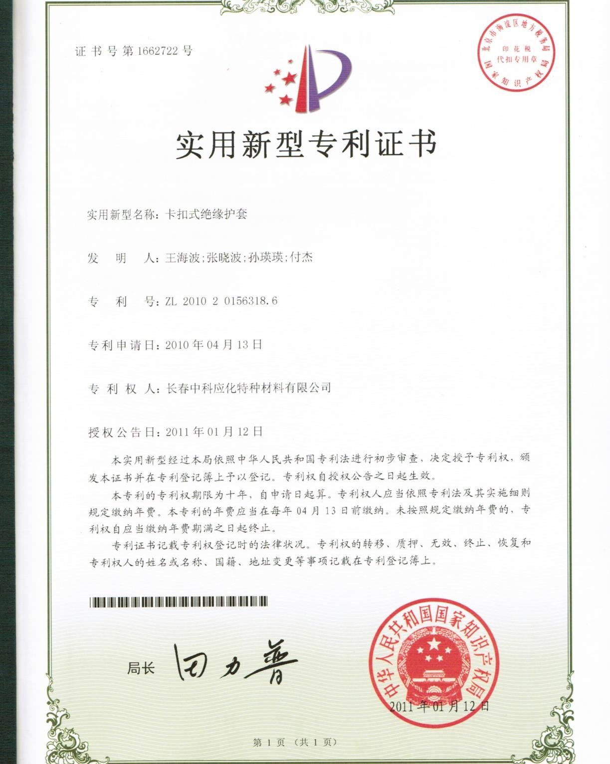
Patent Certificate for SINOFUJI Overhead Line Cover
Application Demonstration (1) of SINOFUJI Overhead Line
Cover
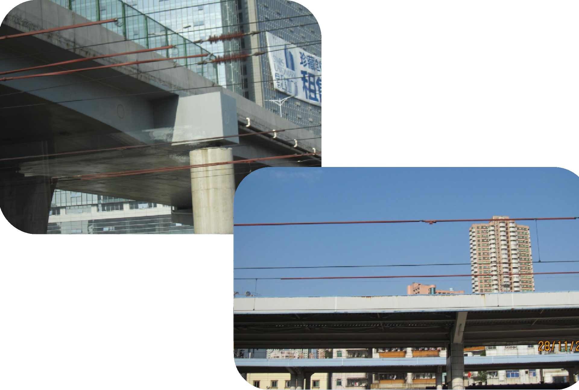
Eliminate the danger due to insufficient safety
distance between the 4-circuit 10kV line and the overpass bridge
Eliminate Potential Danger of Plants to Overhead Line
10KV Overhead Line Cover can be installed without
cutting the power supply.
Eliminate the danger due to insufficient safety
distance between the 10kV line and the Residential buildings.
Application Demonstration (3) of SINOFUJI Overhead Line
Cover
After the power supply is shut down, the overhead line
cover is installed for 35kV overhead line at fixed point.
Application Demonstration (4) of SINOFUJI Overhead Line
Cover
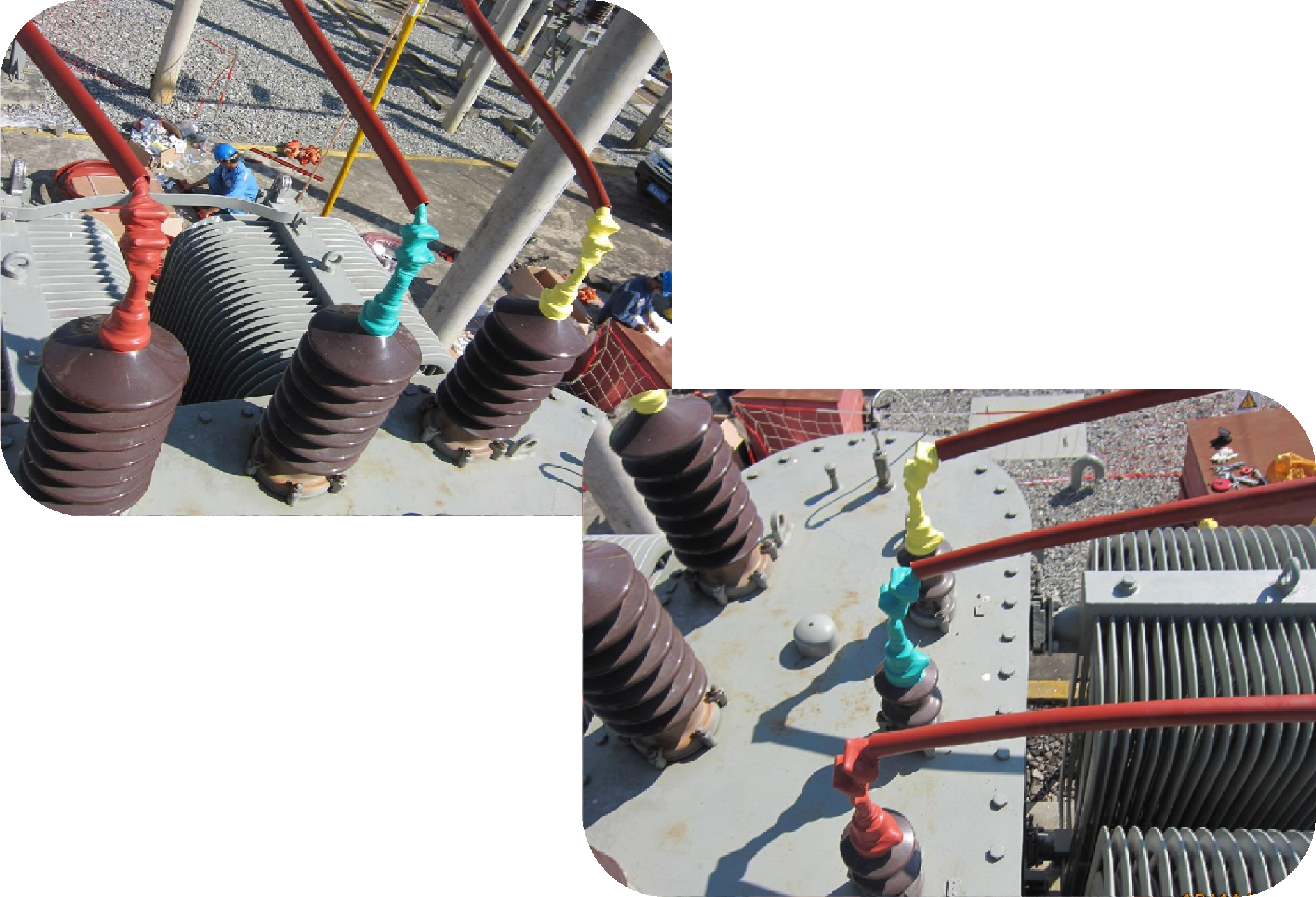
While HB1522 Irradiation crosslinking silicone rubber
self-melting tape is adopted to wrap the various equipment contacts, at the
same time, the SINOFUJI overhead line cover is installed to bare wire with its
voltage 10kv or below for Insulation Upgrading Project of Distribution
Transformer.
Application Demonstration (5) of SINOFUJI Overhead Line
Cover
While HB1522 Irradiation crosslinking silicone rubber
self-melting tape is adopted to jumpers and its tension clamps, at the same
time, the SINOFUJI overhead line cover is installed to bare wire with its
voltage 10kv or below, Thus the comprehensive insulation protection scheme can
be achieved, mainly for the area where electric poles and electric towers are
located.
Application Demonstration (6) of SINOFUJI Overhead Line
Cover
HB1571 SINOFUJI Overhead line Cover is a firstly
made domestic production aiming at construction of
China high-speed railway. The new invention had been obtained national patent.
In the application of the 27.5kV power supply network
of the high-speed railway, it prevents the occurrence of high-speed rail outage
accidents caused by open circuit trips with interfering objects.
Application Demonstration (7) of SINOFUJI Overhead Line
Cover
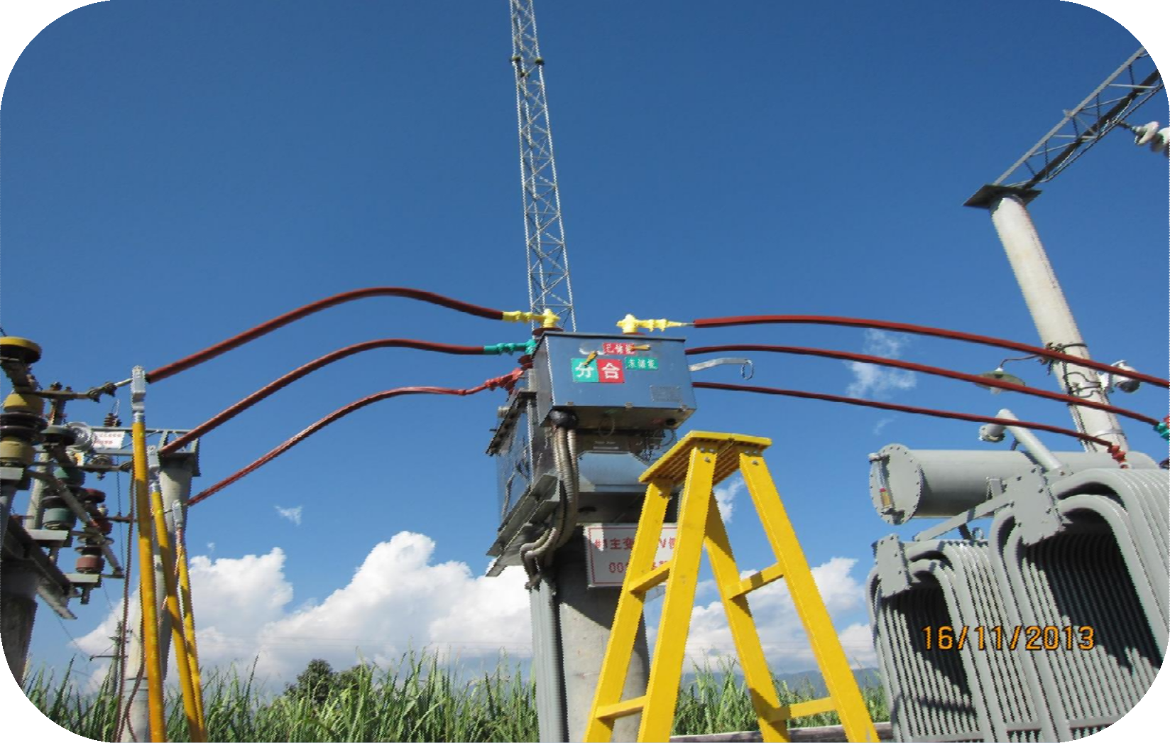
The 35kV overhead line of the outlet side of
substation is installed with SINOFUJI Overhead Line Cover.
The10kV overhead line of the outlet side of substation
is installed with SINOFUJI Overhead Line Cover.
Application Demonstration (8) of SINOFUJI Overhead Line
Cover
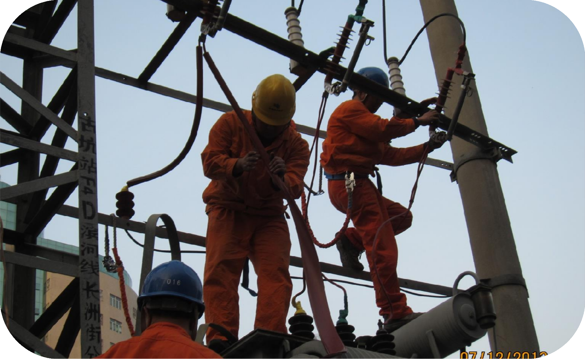
While HB1522 Irradiation crosslinking silicone rubber
self-melting tape is adapted to circuit breaker contacts, at the same time, the
SINOFUJI overhead line cover is installed to 10kv bare wire, thus the
comprehensive insulation protection scheme of bus line of 10KV side of
substation is achieved.
Application Demonstration (9) of SINOFUJI Overhead Line
Cover
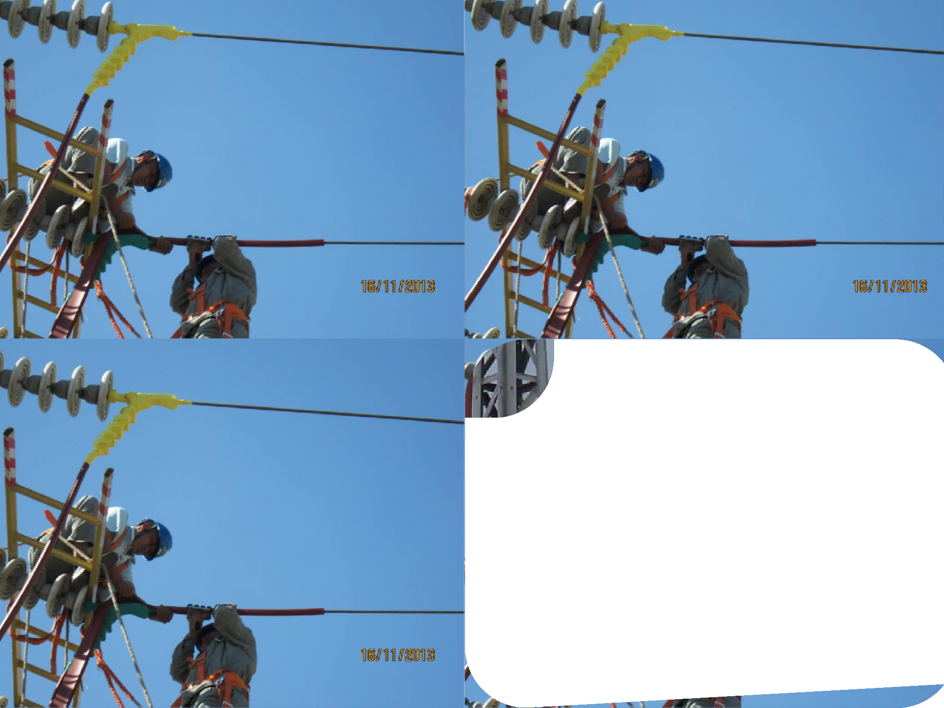
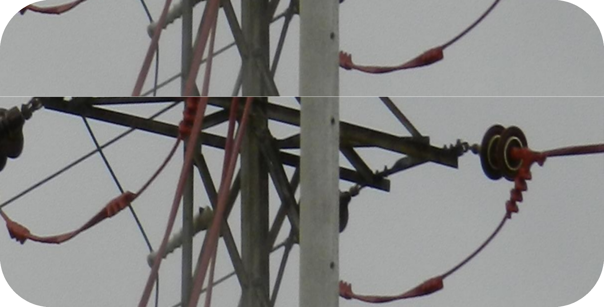
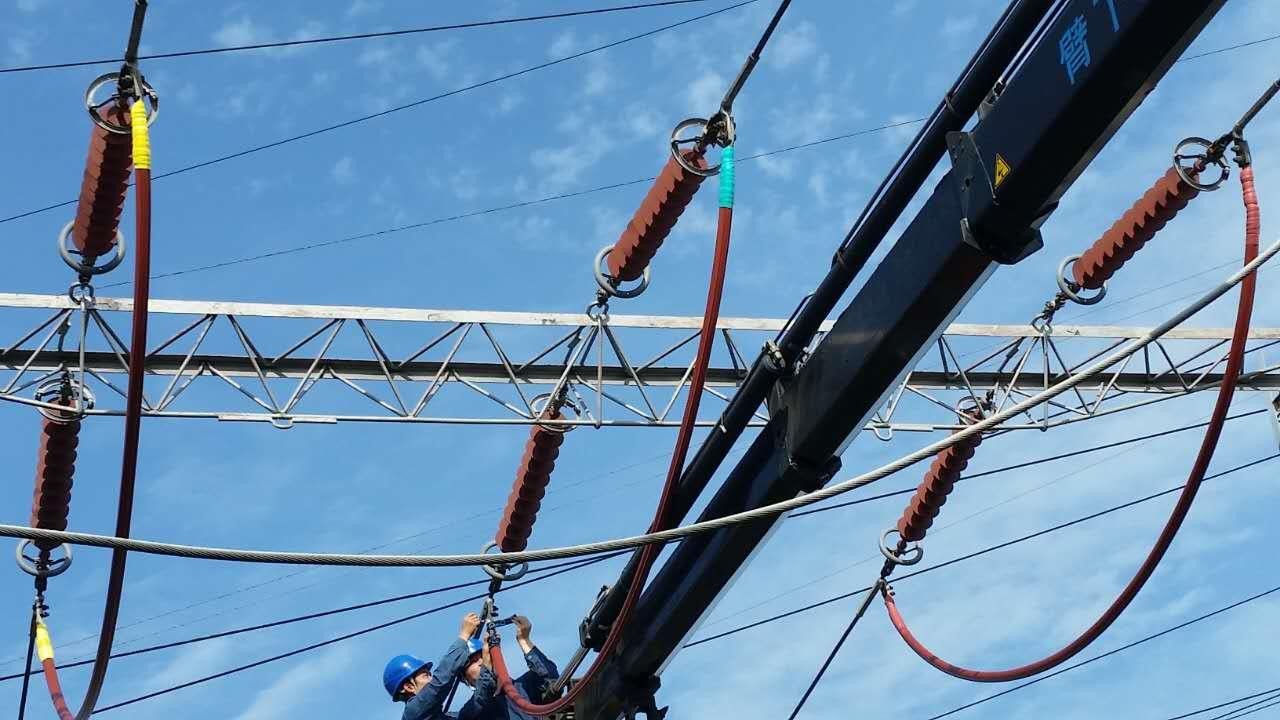
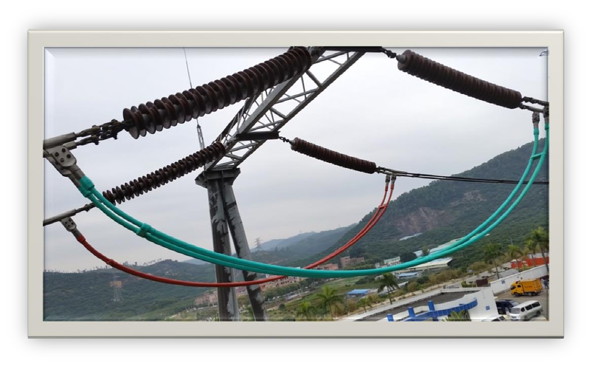
The SINOFUJI Overhead Line Cover is used on the jumper
of high-voltage transmission line to prevent wind deviation, bird damage,
moisture, and salt spray from causing flashover trips and other accidents.
Application Demonstration (10) of SINOFUJI
Overhead Line Cover
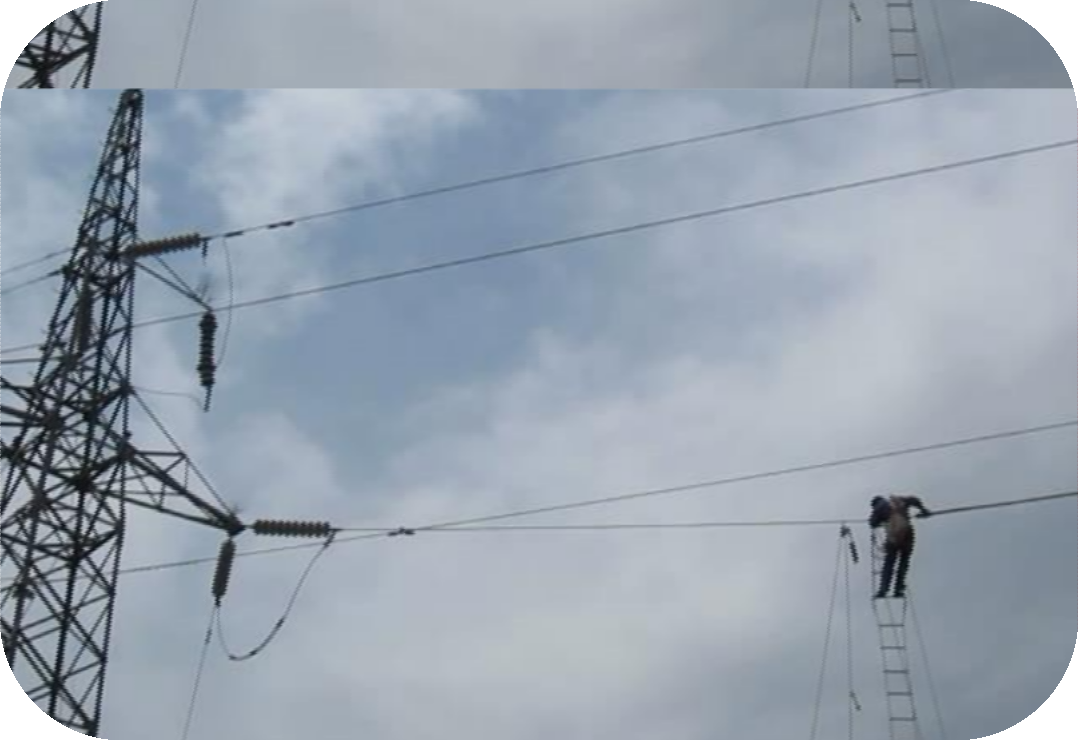
The 110kV
HV overhead line is installed with SINOFUJI Overhead Line Cover.
Application Demonstration (11) of SINOFUJI
Overhead Line Cover
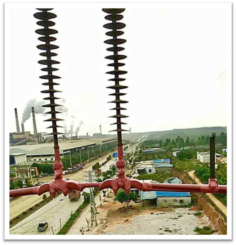
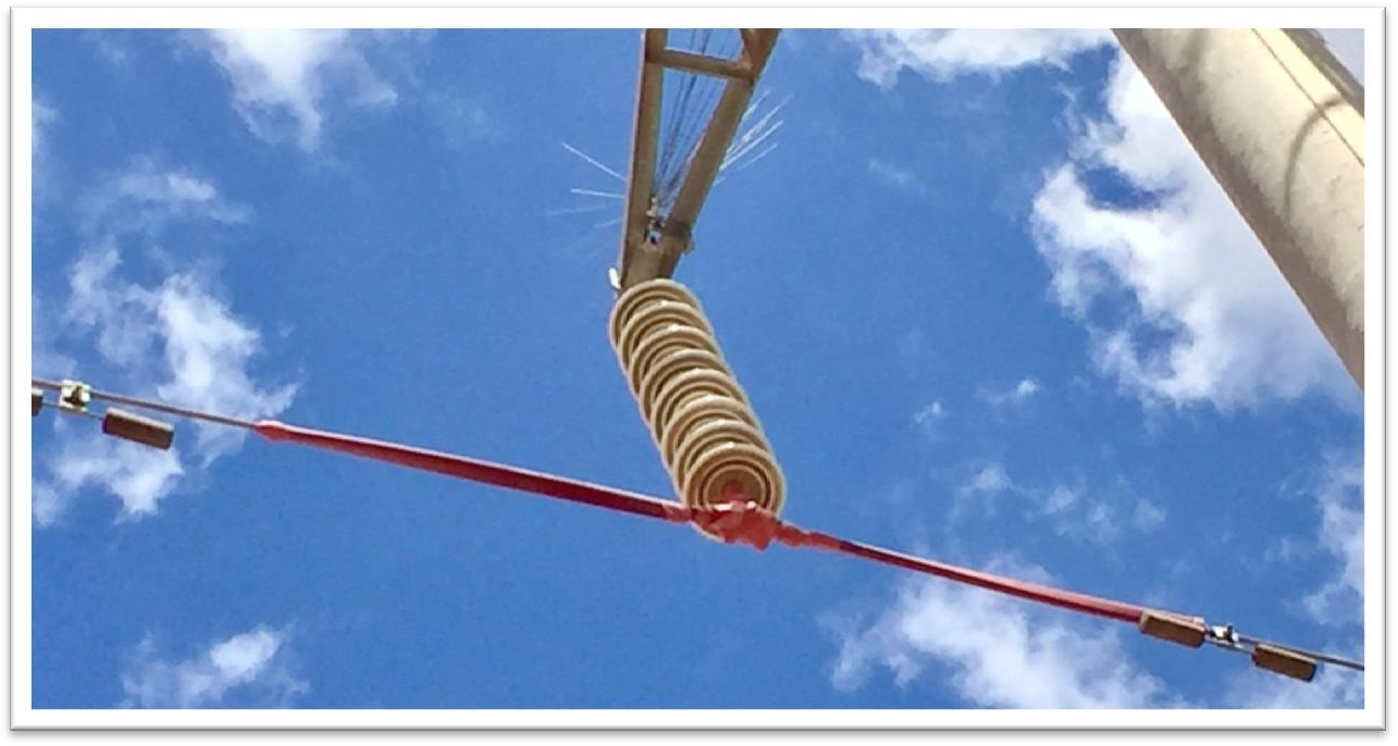
Together with our self made tape, SINOFUJI Overhead
Line Cover is applied to the suspension insulator of 110~220 kV line, which can
increase the Creepage Distance giving consideration to Anti-pollution flashover
and bird-prevention.
Application Demonstration (12) of SINOFUJI
Overhead Line Cover
The
220kV HV overhead line is installed with SINOFUJI Overhead Line Cover.
Silicon Rubber Overhead Line Cover,Waterproof And Insulation Sheath,Overhead Line Cover,Bushing Cover For Overhead Line ShenZhen FUJI Electric Material Co., Ltd , https://www.sinofuji.com
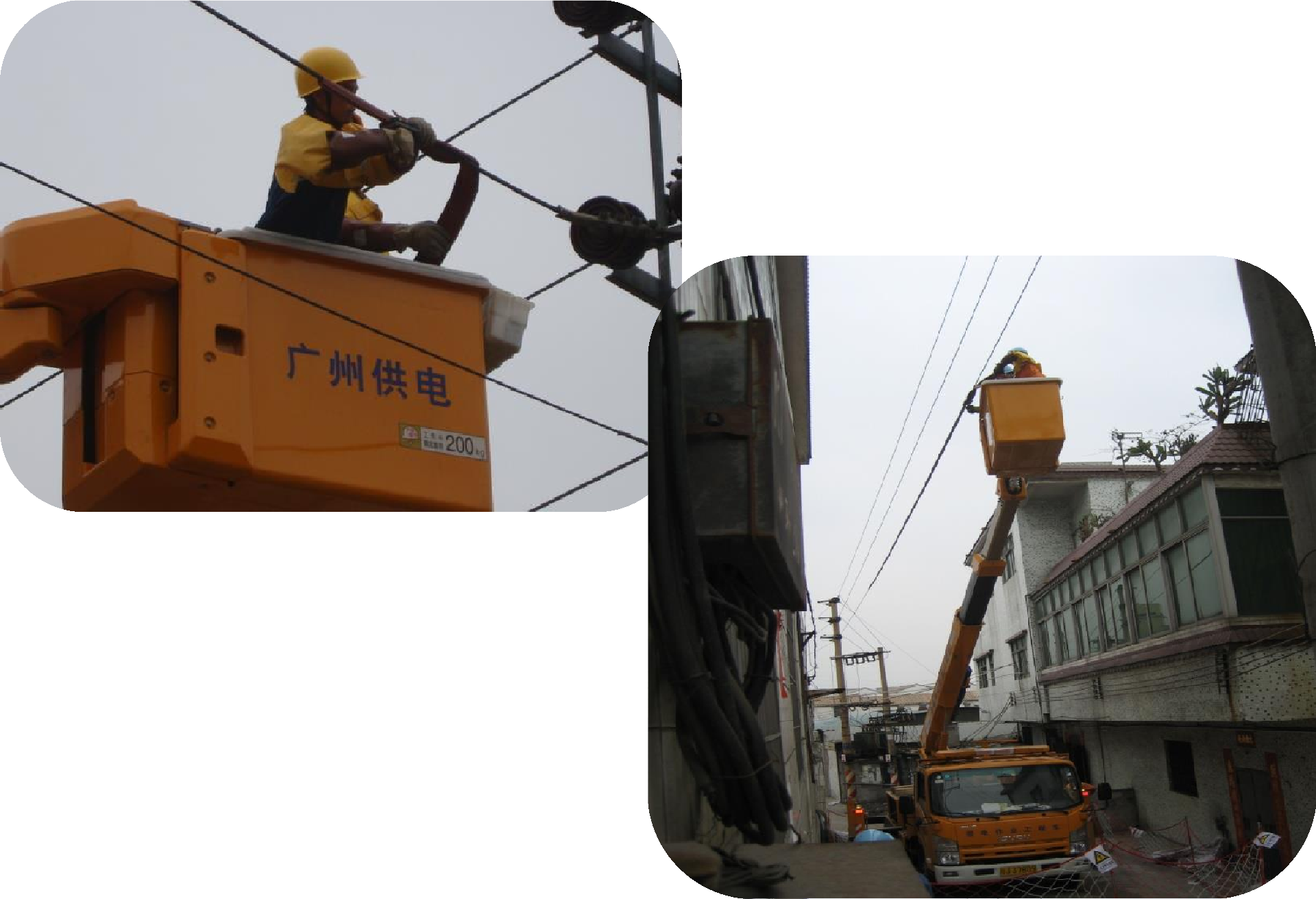
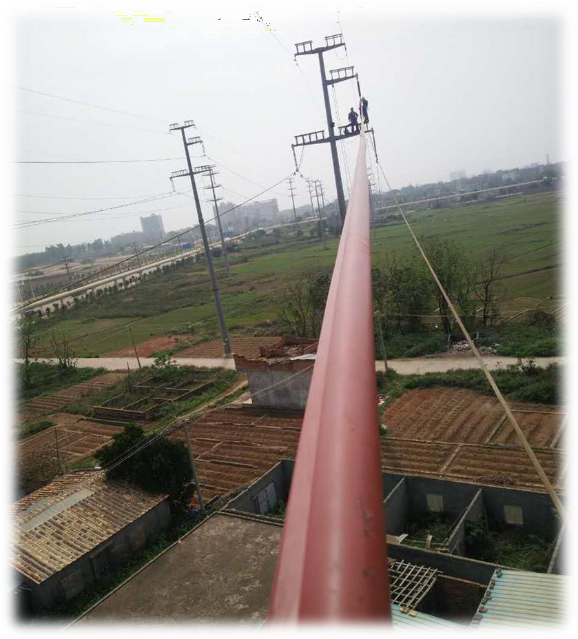
Being equipped with special installation tools with the principle is similar to that of clothe zipper, it can be installed without shut down the power (the voltage is 10kV or below). The operator can install up to 80 meters of overhead line by standing on one fixed position, the installation speed can be reached as high as 20 meters/5 minutes if two people working together in a team.
The sag of overhead line being equipped with SINOFUJI Overhead Line Cover will not exceed the technical requirements, so there is no need to replace any equipment such as braces and clamps.
Excellent weather resistance and insulation, anti-creep, UV resistance, flame retardant, good wear resistance, the lifetime can be guaranteed for ten years.
