Beginners Training Orginal Badminton,Goose Feather Badminton,Flight Stability Badminton,Professional Environmental Glue Badminton ZHEJIANG JUNYE SPORTS GOODS CO.,LTD. , https://www.cnjunbei.com
2 Principles of Fiber Bragg Grating Sensors Fiber grating sensors can both measure temperature and measure strain. Both of these physical quantities can cause changes in the Bragg wavelength of the fiber grating [11].
The temperature sensing characteristics of the fiber grating are caused by the thermo-optic effect and the thermal expansion effect of the fiber grating. The thermo-optic effect causes a change in the effective refractive index of the fiber grating, and the thermal expansion effect causes a change in the grating period of the grating. When the temperature field of the FBG sensor is changed, the influence of temperature on the Bragg wavelength change can be deduced as [12] ![]()
Where a is the thermal expansion coefficient of the optical fiber, which mainly causes the change of the grid period, taking 5.5 Ì10-7; x is the thermal optical coefficient of the optical fiber, which mainly causes the refractive index change of the optical fiber, taking 5.5 Ì10-6. The strain characteristics of fiber Bragg grating sensors are the result of the co-action of the elastic and elastic effects. The elastic effect will change the grid period of the grating. The elastic effect will change the effective refractive index of the fiber. The sensing characteristics can be expressed as [13]. ![]()
3 contact temperature measurement system program 3.1 installation of fiber Bragg grating sensor The breaker of high-voltage switch cabinet is divided into two parts: mobile trolley and switch cabinet. There are six contacts of high-voltage switch cabinet, which are respectively distributed on the upper side and the lower side. On the B and C phases, the temperature of the six contacts must be monitored at the same time in order to ensure the reliability of the system. As shown in equations (1) and (2), since the fiber grating sensor is sensitive to temperature and strain at the same time, in order to ensure the accuracy of temperature measurement, cross-sensitivity effects of strain must be shielded, that is, any strain generated during the separation and combination process of the circuit breaker. Should not be passed to the fiber grating sensor. In this system, the single-ended FBG temperature sensor is fixed on the static contact to shield the strain generated by the contact during the collision. In addition, in order to ensure the uniformity of the FBG temperature sensor's temperature measurement at each point of the contact, the system makes full use of the middle gap of the static contact to fix the temperature sensor in the middle of the static contact. Figure 1 shows the sensor in a single static contact. Installation diagram. When the movable contact and the static contact are separated and combined, strain occurs in the circumferential position of the static contact, and there is no strain in the center, so the strain is not transmitted to the fiber grating sensor. This installation solution not only guarantees the accuracy of temperature measurement but also shields the cross-sensitivity effects due to the strain. 
3.2 Optical path re-use scheme Simultaneous measurement of six fiber-optic-grating temperature sensors involves multiplexing of the optical path. Multiplexing of fiber-optic-grating sensors can use wavelength division multiplexing (WDM), space division multiplexing (SDM), or time division multiplexing. In the (TDM) mode, the system uses space division multiplexing and wavelength division multiplexing. As shown in Fig. 2, a 1 Ì8 coupler is used to realize space division multiplexing of the sensor, so that the disadvantage of using a single wavelength division multiplexing can be avoided, that is, multiple sensors are connected in series on one optical fiber, and one of the sensors is damaged. It will affect the transmission of other sensor signals; at the same time, wavelength division multiplexing is used to select the operating wavelength of the sensor, which is used to increase the measurement speed of the system, that is, one scanning cycle can be used to realize six sensors when the wavelength is demodulated. Simultaneous measurement. 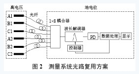
In FIG. 2, six fiber Bragg grating temperature sensors of A, B and C phases are on the high voltage side and are respectively installed in the fixed contact aperture, and the coupler, the wavelength demodulator, the controller, and the data processing circuit are all in On the ground potential side, it is installed in the control room and long-distance optical fiber transmission is used to achieve high voltage side insulation isolation. In the figure, A1, B1, C1, A2, B2, and C2 are the fiber grating temperature sensors designed in this paper. They are distributed on the three phases of the upper and lower sides of the isolation contact A, B, and C, and the wavelength of the sensor at room temperature. They are 1548.5nm, 1550.1nm, 1551.6nm, 1553.5nm, 1555.5nm, 1557.1nm, and the sensitivity is 0.011nm/°C, 0.013nm/°C, 0.011nm/°C, 0.010nm/°C, 0.011nm/°C, 0.012nm/ °C, the measuring range is 0~110 °C; the coupler is a 1 Ì8 coupler composed of 7 3dB couplers; the wavelength demodulator uses the piezoelectric ceramic driving etalon to achieve wavelength scanning, and its working wavelength range is 1548~1558nm, covering all wavelength bands of 6 sensors when the temperature changes from 0 to 110°C; the controller performs scanning of the wavelength demodulator under the control of the data processor.
3.3 Contact temperature model When the high-voltage switchgear is in operation, contacts, busbars, current transformers, cabinets, etc. constitute multiple heat sources, and the high-voltage switchgear and internal components form a complex thermal resistance network [14]. In this system, it is difficult to derive the mathematical relationship between the temperature rise of the contact and the temperature rise of the FBG sensor through the theory. Therefore, the mathematical model between them is established through the test method.
The temperature rise experiment was conducted on a 10kV high voltage switchgear. During the experiment, the three-phase contacts were in normal contact. The rated current was 1kA and the room temperature was 25°C. Fig. 3 is the temperature rise process curve of the B phase of the upper isolation contact. It can be seen that the temperature rise change measured by the fiber grating sensor is slower than the actual temperature rise of the contact, but their change tendency is the same, after about 3 h The temperature field tends to be stable. The difference between the measured temperature and the actual temperature is due to the fact that the sensor measures the temperature in a non-contact manner and it depends on the radiation from the stationary contacts to transfer the heat. Table 1 is the temperature rise measurement data. 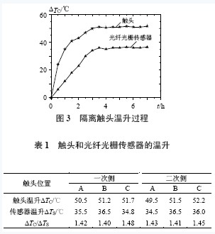
It can be seen that the proportional relationship between the actual temperature rise value DTC of each contact and the corresponding sensor temperature rise value DTS after the contact of the switchgear contact is normal and the temperature change is stable is around 1.43, and the average value is taken as the test result and can be established. The mathematical relationship between the actual temperature of the contact and the measured temperature of the sensor is TC = "K"(TS-T) + T(3)
In the formula, K = "1".43; TS is the temperature value measured by the fiber grating temperature sensor; T is the ambient temperature of the high voltage switch cabinet.
3.4 Analysis of Electromagnetic Interference Resistance of the System In order to test the anti-electromagnetic interference capability of the fiber grating sensing system, the high-voltage switchgear is operated at full load, and the sensor measurement tends to be stable, and the switchgear is suddenly powered off. Detect the relationship between temperature measurement results and electromagnetic fields [15-16], to achieve the experiment of anti-electromagnetic interference ability. Fig. 4 is the temperature data measured on the B-phase contact on the primary side after the temperature rise of the contacts tends to stabilize, and two power cuts are arranged during the test. Fig. 4(a) is a process diagram of the current change, 4(b) is the contact temperature change curve caused by the current change. It can be seen that under the condition that the busbar loses current, the temperature of the contact is reduced, but it quickly begins to rise after the power transmission is resumed. It can be seen from the curves that the measured contact temperature reacts to the sudden power failure and power transmission, but the temperature rise and fall is gradual rather than sudden, indicating that the presence of the electromagnetic field has no effect on the transmission fiber and the fiber grating temperature sensor. . If the presence of the electromagnetic field causes the temperature displayed by the temperature measurement system to be higher or lower than the actual temperature, the temperature display will immediately jump to the “actual value†if the electromagnetic field disappears when the current in the switchgear busbar loses current. The phenomenon of change did not occur in actual tests. Therefore, the fiber grating contact temperature measurement system has strong anti-electromagnetic interference capability.
4 Experimental results The optical fiber grating contact temperature measurement system was successfully tested on the substation 10kV high voltage switchgear. Figure 5 is the temperature of the primary side B phase contact at 24 hours when the high voltage switchgear is working in the 70% rated load range. The monitoring record, which reflects the change of contact temperature throughout the day. It can be seen from the figure that the temperature of the contact between 0 midnight and 6 am is the lowest. This is due to the small electricity load and the low temperature; on the other hand, it starts from 6 am. With the increase of the electric load, the temperature of the contact began to increase. At 9 o'clock, the electric load tended to be stable. However, due to the gradual increase of the temperature, the contact temperature began to rise, and the temperature reached the maximum at 14 o'clock. From 14 Between the 18 o'clock and the 18 o'clock, the temperature of the contact gradually became smaller; at the same time, after 18 o'clock, the temperature of the contact began to rise due to the increase of the electric load, and reached the highest at 22 o'clock; With the reduction of the electrical load, the contact temperature gradually decreases. By recording and analyzing the 24-hour contact temperature, it can be seen that the fiber grating contact temperature measurement system can work normally, and its recorded data correctly reflects the relationship between the contact temperature and the working load of the switchgear and the ambient air temperature. It is illustrated that the solution of the fiber grating contact temperature measurement system is feasible. 
5 conclusions This article uses the advantages of small size, strong immunity to electromagnetic interference, good insulation, etc., instead of electronic sensors to achieve the temperature monitoring of isolated contacts of high-voltage switchgear, this program does not require complex insulation design, so Simple, reliable advantages. In this solution, the strain cross-sensitivity effect of the fiber grating temperature sensor is solved, and a space division multiplexing plus wavelength division multiplexing scheme is adopted in optical path multiplexing to improve the reliability and real-time performance of the system. This system was tested on a 10kV high voltage switchgear and the system was able to operate normally. This shows that this solution is feasible.
Research on Temperature Monitoring of Isolating Contacts in High Voltage Switchgear in Power Industry
I. INTRODUCTION The temperature monitoring of isolated contacts of high-voltage switchgear has always been one of the major issues in the safe operation of the power industry. However, because the contacts are in a strong electromagnetic field and high voltage environment, the current monitoring methods are based on how to achieve the system's resistance. Strong electromagnetic field interference and high voltage isolation problems, the main methods are temperature paper temperature measurement, infrared temperature measurement [1-2], FP optical measurement [3], sensor stealing method [4], optical fiber transmission method and infrared Wireless transmission [5-6] and so on. The FBG sensor sets measurement and transmission in one and adopts the form of light waves for measurement and transmission. It has the advantages of small size, light weight, small transmission loss, immunity to electromagnetic interference, and good insulation performance, and is therefore very suitable for high voltage switch cabinets. Contact temperature measurement environment [7-10]. Based on the above advantages, this paper proposes a contact temperature measurement scheme using a fiber grating temperature sensor, while using a reasonable installation technology to solve the effect of strain cross-sensitivity. In the formula, Pe is the effective elastic coefficient of the fiber, Pe=0.22. Because FBG sensors can both measure temperature and measure strain, when measuring the temperature of high-voltage switchgear isolation contacts, it is necessary to find ways to shield the effect of strain caused by switch cabinet vibration on the accuracy of temperature measurement. This is the optical fiber. The grating sensor is cross-sensitive to strain.